
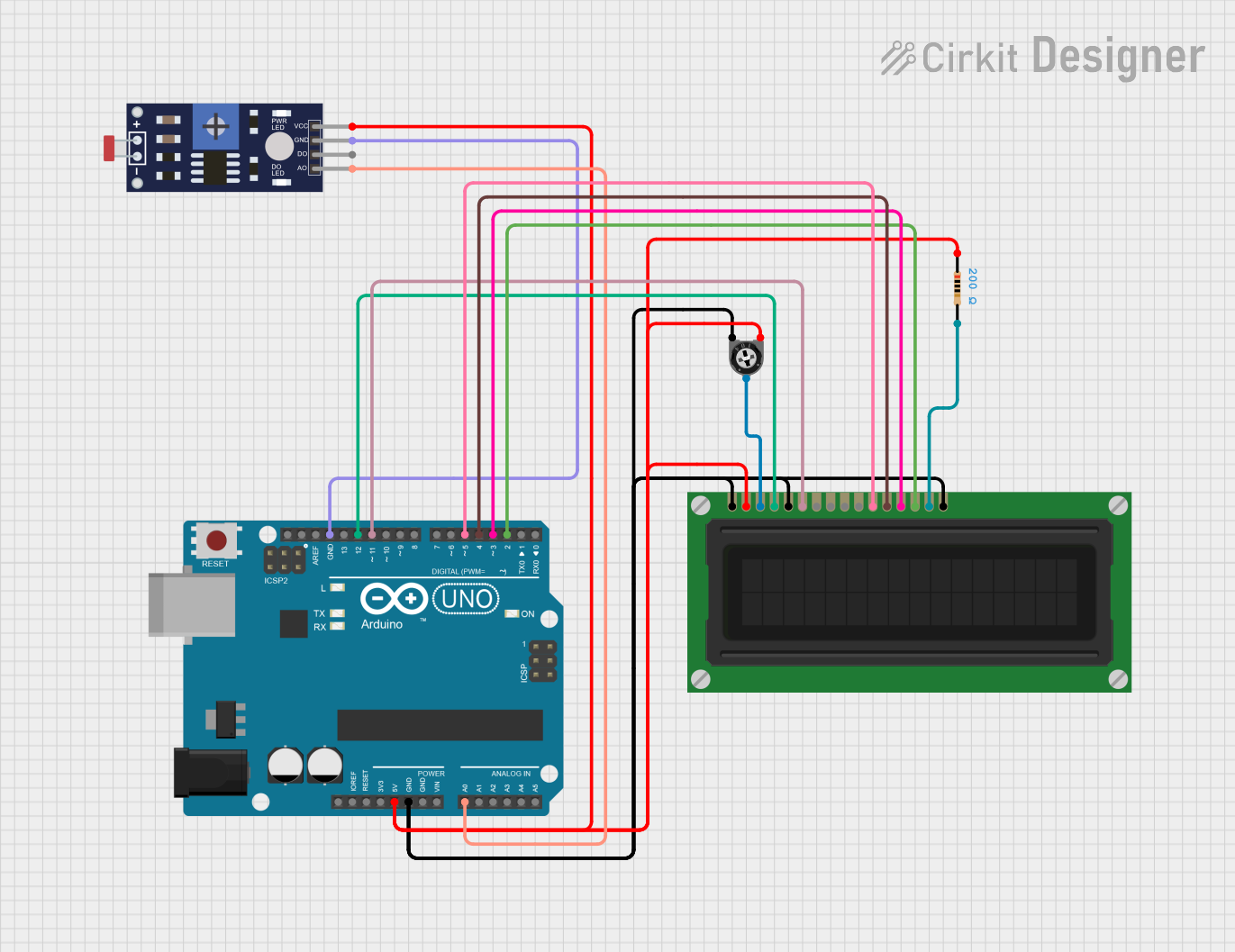
Circuit Documentation
Summary
This circuit is designed to measure the ambient light level using a photoresistor (LDR) and display the light intensity on a 16x2 LCD display. The circuit is controlled by an Arduino UNO microcontroller, which reads the analog value from the LDR, calculates the light intensity in lux, and displays the result on the LCD.
Component List
Arduino UNO
- Description: A microcontroller board based on the ATmega328P.
- Pins: UNUSED, IOREF, Reset, 3.3V, 5V, GND, Vin, A0, A1, A2, A3, A4, A5, SCL, SDA, AREF, D13, D12, D11, D10, D9, D8, D7, D6, D5, D4, D3, D2, D1, D0
Photoresistor (LDR) Sensor (Wokwi Compatible)
- Description: A light-dependent resistor used to measure light intensity.
- Pins: VCC, GND, DO, AO
LCD Display (16 pin)
- Description: A 16x2 character LCD display.
- Pins: VSS, VDD, VO, RS, R_W, E, DB0, DB1, DB2, DB3, DB4, DB5, DB6, DB7, A, K
Trimmer Potentiometer
- Description: A variable resistor used to adjust the contrast of the LCD.
- Pins: leg1, wiper, leg2
- Properties: Resistance: 10,000 Ohms
Resistor
- Description: A fixed resistor used in the circuit.
- Pins: pin1, pin2
- Properties: Resistance: 200 Ohms
Wiring Details
Arduino UNO
5V connected to:
- Photoresistor (LDR) Sensor (VCC)
- Trimmer Potentiometer (leg1)
- Resistor (pin1)
- LCD Display (VDD)
GND connected to:
- Trimmer Potentiometer (leg2)
- LCD Display (VSS)
- LCD Display (K)
- LCD Display (R_W)
- Photoresistor (LDR) Sensor (GND)
A0 connected to:
- Photoresistor (LDR) Sensor (AO)
D12 connected to:
- LCD Display (RS)
D11 connected to:
- LCD Display (E)
D5 connected to:
- LCD Display (DB4)
D4 connected to:
- LCD Display (DB5)
D3 connected to:
- LCD Display (DB6)
D2 connected to:
- LCD Display (DB7)
Photoresistor (LDR) Sensor (Wokwi Compatible)
VCC connected to:
- Arduino UNO (5V)
GND connected to:
- Arduino UNO (GND)
AO connected to:
- Arduino UNO (A0)
LCD Display (16 pin)
VDD connected to:
- Arduino UNO (5V)
VSS connected to:
- Arduino UNO (GND)
VO connected to:
- Trimmer Potentiometer (wiper)
RS connected to:
- Arduino UNO (D12)
R_W connected to:
- Arduino UNO (GND)
E connected to:
- Arduino UNO (D11)
DB4 connected to:
- Arduino UNO (D5)
DB5 connected to:
- Arduino UNO (D4)
DB6 connected to:
- Arduino UNO (D3)
DB7 connected to:
- Arduino UNO (D2)
A connected to:
- Resistor (pin2)
K connected to:
- Arduino UNO (GND)
Trimmer Potentiometer
leg1 connected to:
- Arduino UNO (5V)
leg2 connected to:
- Arduino UNO (GND)
wiper connected to:
- LCD Display (VO)
Resistor
pin1 connected to:
- Arduino UNO (5V)
pin2 connected to:
- LCD Display (A)
Code Documentation
#include <LiquidCrystal.h>

// Define the pins for the 16-pin LCD
const int rs = 12, en = 11, d4 = 5, d5 = 4, d6 = 3, d7 = 2;

// Initialize the LCD library with the numbers of the interface pins
LiquidCrystal lcd(rs, en, d4, d5, d6, d7);

#define LDR_PIN A0

// LDR Characteristics
const float GAMMA = 0.7;
const float RL10 = 50;

void setup() {
    pinMode(8, OUTPUT);
    pinMode(9, OUTPUT);
    digitalWrite(8, LOW);
    digitalWrite(9, HIGH);

    pinMode(LDR_PIN, INPUT);

    lcd.begin(16, 2); // Initialize the LCD with 16 columns and 2 rows
}

void loop() {
    int analogValue = analogRead(A0);
    float voltage = analogValue / 1024. * 5;
    float resistance = 2000 * voltage / (1 - voltage / 5);
    float lux = pow(RL10 * 1e3 * pow(10, GAMMA) / resistance, (1 / GAMMA));

    lcd.setCursor(2, 0);
    lcd.print("Room: ");
    if (lux > 50) {
        lcd.print("Light!");
    } else {
        lcd.print("Dark  ");
    }

    lcd.setCursor(0, 1);
    lcd.print("Lux: ");
    lcd.print(lux);
    lcd.print("          ");

    delay(100);
}
This code initializes the LCD and reads the analog value from the LDR. It then calculates the light intensity in lux and displays the result on the LCD. The setup function initializes the pins and the LCD, while the loop function continuously reads the LDR value, calculates the lux, and updates the LCD display.