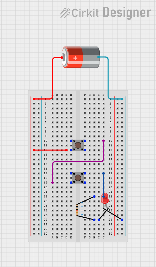
Pushbutton-Controlled LED Circuit with Resistor

Circuit Documentation
Summary of the Circuit
The circuit described by the provided inputs is a simple LED control circuit powered by a 5V battery. It includes two pushbuttons, a resistor, and a red LED. The pushbuttons are used to control the flow of current to the LED. When a pushbutton is pressed, it closes the circuit allowing current to flow through the resistor to the LED, causing it to light up. The resistor is used to limit the current to the LED to prevent it from burning out.
Component List
Pushbutton
- Description: A pushbutton is a momentary switch that completes a circuit when pressed.
- Pins:
- Pin 1 (in): Input pin connected to the positive terminal of the battery or another pushbutton's output.
- Pin 2 (in): Not used in this circuit.
- Pin 3 (out): Not used in this circuit.
- Pin 4 (out): Output pin connected to another pushbutton's input or a resistor.
Resistor
- Description: A resistor is a passive two-terminal electrical component that implements electrical resistance as a circuit element.
- Resistance: 80 Ohms
- Pins:
- pin1: Connected to a pushbutton's output.
- pin2: Connected to the anode of the LED.
LED: Two Pin (red)
- Description: A light-emitting diode (LED) is a semiconductor light source that emits light when current flows through it.
- Pins:
- cathode: Connected to the negative terminal of the battery.
- anode: Connected to the resistor.
5v Battery
- Description: A 5V battery provides the power source for the circuit.
- Pins:
- (positive terminal): Connected to a pushbutton's input.
- (negative terminal): Connected to the cathode of the LED.
Wiring Details
Pushbutton
- Pin 1 (in): Connected to the positive terminal of the 5v Battery.
- Pin 4 (out): Connected to the input of another Pushbutton or the pin1 of the Resistor.
Resistor
- pin1: Connected to the output (Pin 4) of a Pushbutton.
- pin2: Connected to the anode of the LED: Two Pin (red).
LED: Two Pin (red)
- cathode: Connected to the negative terminal of the 5v Battery.
- anode: Connected to pin2 of the Resistor.
5v Battery
- + (positive terminal): Connected to the input (Pin 1) of a Pushbutton.
- - (negative terminal): Connected to the cathode of the LED: Two Pin (red).
Documented Code
There is no microcontroller or embedded code provided for this circuit. Therefore, this section is not applicable to the current documentation.
This documentation provides an overview of the circuit's components, their descriptions, and the wiring details that interconnect them. The absence of a microcontroller simplifies the circuit, making it purely hardware-based with no programmable control logic.