
Arduino Mega 2560-Based Dual Solenoid Control System with Pushbutton Activation
View and Edit Project In Cirkit Designer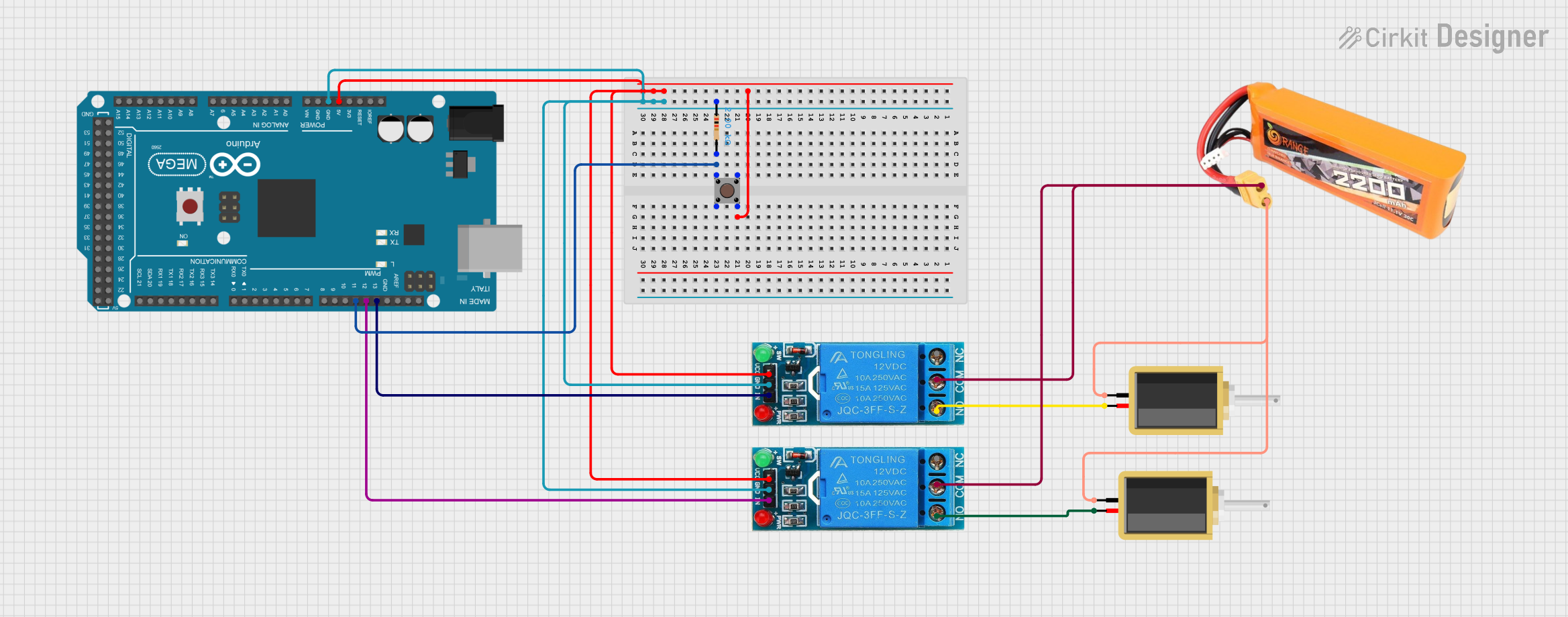
Circuit Documentation
Summary
This circuit involves an Arduino Mega 2560 microcontroller, a pushbutton, resistors, relays, solenoids, and a LiPo battery. The Arduino controls the relays, which in turn control the solenoids. The pushbutton is used to trigger actions on the Arduino, and the resistors are used for current limiting.
Component List
Arduino Mega 2560
- Description: A microcontroller board based on the ATmega2560.
- Pins: IOREF, RESET, 3V3, 5V, GND, VIN, A0-A15, D21/SCL, D20/SDA, D19/RX1, D18/TX1, D17 PWM/RX2, D16 PWM/TX2, D15/RX3, D14/TX3, D0 RX0, D1 TX0, D2 PWM, D3 PWM, D4 PWM, D5 PWM, D6 PWM, D7 PWM, D8 PWM, D9 PWM, D10 PWM, D11 PWM, D12 PWM, D13 PWM, AREF, SDA, SCL, D52, D50, D48, D46, D44, D42, D40, D38, D36, D34, D32, D30, D28, D26, D24, D22, D53, D51, D49, D47, D45, D43, D41, D39, D37, D35, D33, D31, D29, D27, D25, D23
Resistor
- Description: A 2000 Ohm resistor.
- Pins: pin1, pin2
- Properties: Resistance: 2000 Ohms
Pushbutton
- Description: A simple pushbutton switch.
- Pins: Pin 3 (out), Pin 4 (out), Pin 1 (in), Pin 2 (in)
12V Single Channel Relay
- Description: A relay module for switching high voltage devices.
- Pins: NC, COM, NO, IN, GND, VCC
Solenoid
- Description: An electromechanical solenoid.
- Pins: pin1, pin2
LiPo Battery 2200mAH 30C
- Description: A 2200mAh LiPo battery.
- Pins: VCC, GND
Wiring Details
Arduino Mega 2560
5V is connected to:
- Pushbutton Pin 4 (out)
- VCC of both 12V Single Channel Relays
GND is connected to:
- GND of both 12V Single Channel Relays
- pin1 of the Resistor
D11 PWM is connected to:
- pin2 of the Resistor
- Pushbutton Pin 1 (in)
D12 PWM is connected to:
- IN of the first 12V Single Channel Relay
D13 PWM is connected to:
- IN of the second 12V Single Channel Relay
Resistor
pin1 is connected to:
- GND of both 12V Single Channel Relays
- GND of Arduino Mega 2560
pin2 is connected to:
- Pushbutton Pin 1 (in)
- D11 PWM of Arduino Mega 2560
Pushbutton
Pin 4 (out) is connected to:
- 5V of Arduino Mega 2560
- VCC of both 12V Single Channel Relays
Pin 1 (in) is connected to:
- pin2 of the Resistor
- D11 PWM of Arduino Mega 2560
12V Single Channel Relay
VCC is connected to:
- 5V of Arduino Mega 2560
- Pushbutton Pin 4 (out)
GND is connected to:
- GND of Arduino Mega 2560
- pin1 of the Resistor
IN of the first relay is connected to:
- D12 PWM of Arduino Mega 2560
IN of the second relay is connected to:
- D13 PWM of Arduino Mega 2560
COM of both relays is connected to:
- VCC of the LiPo Battery
NO of the first relay is connected to:
- pin2 of the first Solenoid
NO of the second relay is connected to:
- pin2 of the second Solenoid
Solenoid
pin1 of both solenoids is connected to:
- GND of the LiPo Battery
pin2 of the first solenoid is connected to:
- NO of the first 12V Single Channel Relay
pin2 of the second solenoid is connected to:
- NO of the second 12V Single Channel Relay
LiPo Battery
VCC is connected to:
- COM of both 12V Single Channel Relays
GND is connected to:
- pin1 of both Solenoids
Documented Code
Arduino Mega 2560 Code (sketch.ino)
void setup() {
  // put your setup code here, to run once:

}

void loop() {
  // put your main code here, to run repeatedly:

}
Documentation (documentation.txt)
This documentation provides a comprehensive overview of the circuit, including a detailed list of components, their wiring connections, and the code used in the microcontroller.