
ESP32-Based Smart Lock System with Load Cell and LCD Display
View and Edit Project In Cirkit Designer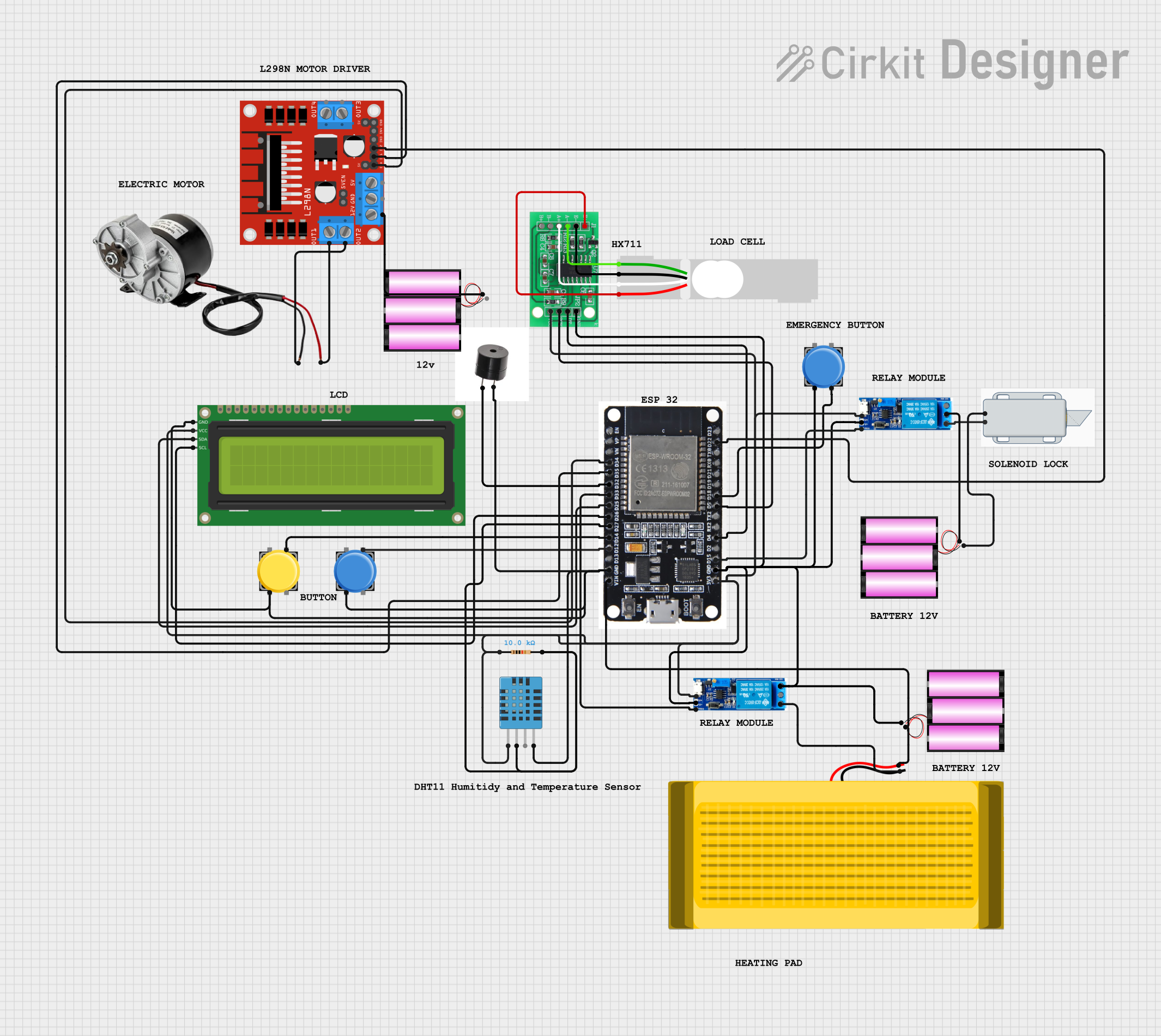
Circuit Documentation
Summary
This circuit is designed to control a 12V solenoid lock and a 250W DC motor using an ESP32 microcontroller. The circuit also includes a 16x2 I2C LCD for display, a DHT11 sensor for temperature and humidity measurement, a buzzer for audio alerts, and a load cell with an HX711 interface for weight measurement. The ESP32 reads the weight from the load cell and controls the relay module to lock or unlock the solenoid based on the weight threshold. The motor is controlled via an L298N motor driver.
Component List
ESP32
- Description: Microcontroller with Wi-Fi and Bluetooth capabilities.
- Pins: EN, VP, VN, D34, D35, D32, D33, D25, D26, D27, D14, D12, D13, GND, VIN, 3V3, D15, D2, D4, RX2, TX2, D5, D18, D19, D21, RX0, TX0, D22, D23, BOOT
16x2 I2C LCD
- Description: 16x2 character LCD with I2C interface.
- Pins: GND, VCC, SDA, SCL
Pushbutton
- Description: Simple pushbutton switch.
- Pins: Pin 2, Pin 1, Pin 3, Pin 4
Relay Module 5V-30V
- Description: Relay module for switching high voltage devices.
- Pins: Common contact, Normally open, Normally closed, Trigger, V-, V+
Battery 12V
- Description: 12V battery for power supply.
- Pins: +, -
DHT11 Humidity and Temperature Sensor
- Description: Sensor for measuring temperature and humidity.
- Pins: VDD, DATA, NULL, GND
Resistor
- Description: 10k Ohm resistor.
- Pins: pin1, pin2
- Properties: Resistance: 10000 Ohms
SparkFun Heating Pad
- Description: Heating pad for providing heat.
- Pins: None
Buzzer
- Description: Buzzer for audio alerts.
- Pins: +, GND
250W 12V Electric Motor Brush Motor DC
- Description: High power DC motor.
- Pins: POSITIF, NEGATIF
12V Solenoid Lock
- Description: Solenoid lock for locking mechanism.
- Pins: -, +
Load Cell - Red/White/Black/Green
- Description: Load cell for weight measurement.
- Pins: E+, A-, E-, A+
HX711 - Bridge Sensor Interface
- Description: Interface for load cell.
- Pins: E+, E-, A-, A+, B-, B+, GND - GROUND, DATA (OUT), SCK - CLOCK (IN), 3.3/3.5V Supply
L298N DC Motor Driver
- Description: Motor driver for controlling DC motors.
- Pins: OUT1, OUT2, 12V, GND, 5V, OUT3, OUT4, 5V-ENA-JMP-I, 5V-ENA-JMP-O, +5V-J1, +5V-J2, ENA, IN1, IN2, IN3, IN4, ENB
Wiring Details
ESP32
- D34: Connected to ENA pin of L298N DC motor driver.
- D35: Connected to IN1 pin of L298N DC motor driver.
- D32: Connected to + pin of Buzzer.
- D33: Connected to Trigger pin of Relay module.
- D25: Connected to SDA pin of 16x2 I2C LCD.
- D26: Connected to SCL pin of 16x2 I2C LCD.
- D27: Connected to DATA pin of DHT11 Humidity and Temperature Sensor and pin2 of Resistor.
- D14: Connected to Pin 3 of Pushbutton.
- D12: Connected to Pin 3 of another Pushbutton.
- GND: Connected to GND pins of Buzzer, Pushbuttons, 16x2 I2C LCD, DHT11 Humidity and Temperature Sensor, and V- pin of Relay module.
- VIN: Connected to SparkFun Heating Pad and + pin of 12V battery.
- 3V3: Connected to VCC pin of 16x2 I2C LCD, VDD pin of DHT11 Humidity and Temperature Sensor, pin1 of Resistor, and V+ pin of Relay module.
- D15: Connected to Trigger pin of another Relay module.
- D4: Connected to DATA (OUT) pin of HX711 - Bridge Sensor Interface.
- D5: Connected to SCK - CLOCK (IN) pin of HX711 - Bridge Sensor Interface.
- D18: Connected to Pin 4 of another Pushbutton.
- D22: Connected to IN2 pin of L298N DC motor driver.
16x2 I2C LCD
- GND: Connected to GND pin of ESP32.
- VCC: Connected to 3V3 pin of ESP32.
- SDA: Connected to D25 pin of ESP32.
- SCL: Connected to D26 pin of ESP32.
Pushbutton
- Pin 2: Connected to GND pin of ESP32.
- Pin 3: Connected to D14 pin of ESP32.
Another Pushbutton
- Pin 2: Connected to GND pin of ESP32.
- Pin 3: Connected to D12 pin of ESP32.
Another Pushbutton
- Pin 2: Connected to GND pin of ESP32.
- Pin 4: Connected to D18 pin of ESP32.
Relay Module 5V-30V
- Trigger: Connected to D33 pin of ESP32.
- V+: Connected to 3V3 pin of ESP32.
- V-: Connected to GND pin of ESP32.
Another Relay Module 5V-30V
- Trigger: Connected to D15 pin of ESP32.
- V+: Connected to 3V3 pin of ESP32.
- V-: Connected to GND pin of ESP32.
- Normally Open: Connected to SparkFun Heating Pad.
- Common Contact: Connected to + pin of 12V battery.
Battery 12V
- +: Connected to VIN pin of ESP32 and Common Contact pin of Relay module.
- -: Connected to GND pin of ESP32 and - pin of 12V Solenoid Lock.
DHT11 Humidity and Temperature Sensor
- VDD: Connected to 3V3 pin of ESP32.
- DATA: Connected to D27 pin of ESP32.
- GND: Connected to GND pin of ESP32.
Resistor
- pin1: Connected to 3V3 pin of ESP32.
- pin2: Connected to D27 pin of ESP32.
SparkFun Heating Pad
- Pin: Connected to VIN pin of ESP32 and Normally Open pin of Relay module.
Buzzer
- +: Connected to D32 pin of ESP32.
- GND: Connected to GND pin of ESP32.
250W 12V Electric Motor Brush Motor DC
- POSITIF: Connected to OUT1 pin of L298N DC motor driver.
- NEGATIF: Connected to OUT2 pin of L298N DC motor driver.
12V Solenoid Lock
- +: Connected to Normally Open pin of Relay module.
- -: Connected to - pin of 12V battery.
Load Cell - Red/White/Black/Green
- E+: Connected to E+ pin of HX711 - Bridge Sensor Interface.
- A-: Connected to A+ pin of HX711 - Bridge Sensor Interface.
- E-: Connected to E- pin of HX711 - Bridge Sensor Interface.
- A+: Connected to A- pin of HX711 - Bridge Sensor Interface.
HX711 - Bridge Sensor Interface
- E+: Connected to E+ pin of Load Cell.
- E-: Connected to E- pin of Load Cell.
- A-: Connected to A+ pin of Load Cell.
- A+: Connected to A- pin of Load Cell.
- DATA (OUT): Connected to D4 pin of ESP32.
- SCK - CLOCK (IN): Connected to D5 pin of ESP32.
- 3.3/3.5V Supply: Connected to 3V3 pin of ESP32.
- GND - GROUND: Connected to GND pin of ESP32.
L298N DC Motor Driver
- ENA: Connected to D34 pin of ESP32.
- IN1: Connected to D35 pin of ESP32.
- IN2: Connected to D22 pin of ESP32.
- OUT1: Connected to POSITIF pin of 250W 12V Electric Motor Brush Motor DC.
- OUT2: Connected to NEGATIF pin of 250W 12V Electric Motor