ESP32-CAM Controlled Solenoid Lock with Relay and Wi-Fi Connectivity
Circuit Documentation
Summary
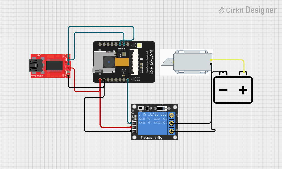
The circuit in question is designed to control a 12V Solenoid Lock using an ESP32-CAM microcontroller, which is capable of image processing and Wi-Fi communication. The ESP32-CAM is interfaced with a ProtoSnap - Pro Mini - FTDI for programming purposes and a 1-Channel Relay to drive the solenoid lock. The system is powered by a 12V battery, which provides power to both the solenoid lock and the relay, while the ESP32-CAM and ProtoSnap are powered by a regulated 5V derived from the relay module.
Component List
12V Solenoid Lock
- Description: An electromechanical lock that is actuated by a 12V signal.
- Purpose: To lock or unlock a physical mechanism when energized.
ESP32 - CAM
- Description: A small-sized ESP32-based board with an integrated camera and Wi-Fi capabilities.
- Purpose: To process images for facial recognition and control the relay based on the recognition result.
ProtoSnap - Pro Mini - FTDI
- Description: A breakout board used for programming the ESP32-CAM via serial communication.
- Purpose: To upload code to the ESP32-CAM.
1-Channel Relay (5V 10A)
- Description: An electromechanical switch that can be controlled by a low-power signal from the ESP32-CAM.
- Purpose: To safely switch the higher power circuit of the solenoid lock.
12V Battery
- Description: A power source providing a 12V output.
- Purpose: To supply power to the solenoid lock and the relay module.
Wiring Details
12V Solenoid Lock
- "+" (Positive): Connected to the "+" terminal of the 12V battery.
- "-" (Negative): Connected to the "C" (Common) terminal of the 1-Channel Relay.
ESP32 - CAM
- "5V": Connected to the "power" terminal of the 1-Channel Relay.
- "GND": Connected to the "ground" terminal of the 1-Channel Relay.
- "IO4": Connected to the "signal" terminal of the 1-Channel Relay to control the relay actuation.
- "VOT": Connected to the "RXI" pin of the ProtoSnap - Pro Mini - FTDI for serial communication.
- "VOR": Connected to the "TXO" pin of the ProtoSnap - Pro Mini - FTDI for serial communication.
ProtoSnap - Pro Mini - FTDI
- "VCC": Connected to the "power" terminal of the 1-Channel Relay.
- "GND": Connected to the "ground" terminal of the 1-Channel Relay.
- "RXI": Connected to the "VOT" pin of the ESP32 - CAM for serial communication.
- "TXO": Connected to the "VOR" pin of the ESP32 - CAM for serial communication.
1-Channel Relay (5V 10A)
- "NO" (Normally Open): Connected to the "-" terminal of the 12V battery.
- "C" (Common): Connected to the "-" terminal of the 12V Solenoid Lock.
- "power": Connected to the "5V" pin of the ESP32 - CAM and "VCC" pin of the ProtoSnap - Pro Mini - FTDI.
- "ground": Connected to the "GND" pin of the ESP32 - CAM and "GND" pin of the ProtoSnap - Pro Mini - FTDI.
- "signal": Connected to the "IO4" pin of the ESP32 - CAM to receive control signals.
12V Battery
- "+" (Positive): Connected to the "+" terminal of the 12V Solenoid Lock.
- "-" (Negative): Connected to the "NO" (Normally Open) terminal of the 1-Channel Relay.
Documented Code
ESP32 - CAM Code (sketch.ino)
#include "esp_camera.h"
#include <WiFi.h>

// Select camera model
#define CAMERA_MODEL_AI_THINKER
#include "camera_pins.h"

const char* ssid = "Galaxy-M20";
const char* password = "ac312124";

#define LED_BUILTIN 4
#define relay 4
#define buzzer 2

boolean matchFace = false;
boolean activeRelay = false;
long prevMillis = 0;
int interval = 5000;

void startCameraServer();

void setup() {
  Serial.begin(115200);
  Serial.setDebugOutput(true);
  Serial.println();

  pinMode(relay, OUTPUT);
  pinMode(buzzer, OUTPUT);
  pinMode (LED_BUILTIN, OUTPUT);

  digitalWrite(LED_BUILTIN, LOW);
  digitalWrite(relay, LOW);
  digitalWrite(buzzer, LOW);

  // Camera configuration
  camera_config_t config;
  // ... (configuration code omitted for brevity)

  // Camera initialization
  esp_err_t err = esp_camera_init(&config);
  if (err != ESP_OK) {
    Serial.printf("Camera init failed with error 0x%x", err);
    return;
  }

  // Sensor settings
  sensor_t * s = esp_camera_sensor_get();
  // ... (sensor configuration code omitted for brevity)

  // Wi-Fi connection
  WiFi.begin(ssid, password);
  while (WiFi.status() != WL_CONNECTED) {
    delay(500);
    Serial.print(".");
  }
  Serial.println("");
  Serial.println("WiFi connected");

  startCameraServer();

  Serial.print("Camera Ready! Use 'http://");
  Serial.print(WiFi.localIP());
  Serial.println("' to connect");
}

void loop() {
  if (matchFace == true && activeRelay == false){
    activeRelay = true;
    digitalWrite (relay, HIGH);
    digitalWrite (buzzer, HIGH);
    delay(800);
    digitalWrite (buzzer, LOW);
    prevMillis = millis();
  }
  if(activeRelay == true && millis()- prevMillis > interval){
    activeRelay = false;
    matchFace = false;
    digitalWrite(relay, LOW);
  }
}
Note: The code provided is a partial representation of the actual code used in the ESP32-CAM. It includes the setup for the camera, Wi-Fi connection, and the main loop that controls the relay and buzzer based on facial recognition (matchFace variable). The actual facial recognition implementation and the startCameraServer function are not included in the provided code snippet.