
ESP32-Based Interactive Display with Sensor Feedback and Motor Control
View and Edit Project In Cirkit Designer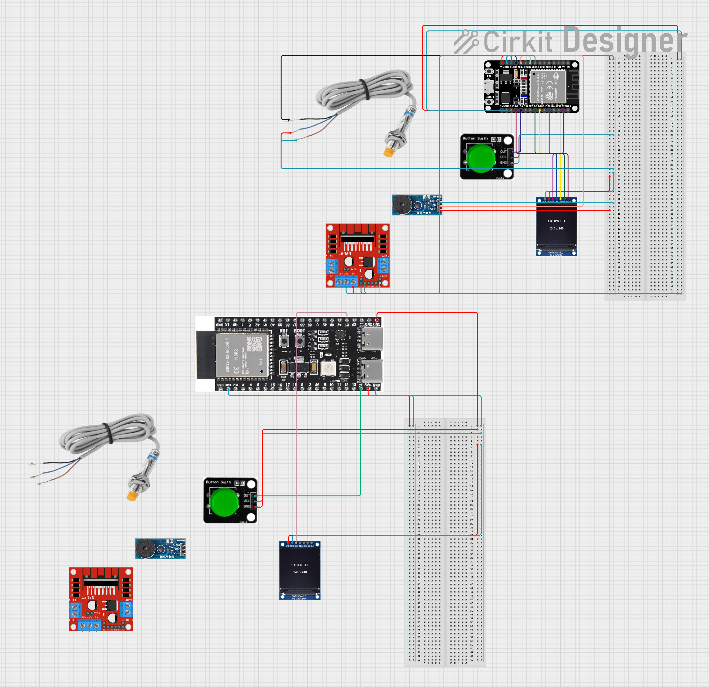
Circuit Documentation
Summary
This circuit integrates a variety of components including microcontrollers, a motor driver, sensors, a display module, and user interface elements. The primary microcontroller is an ESP32 (30 pin) which interfaces with a TFT display module, a buzzer module, an inductive sensor, and a motor driver (L298N). Additionally, there is an ESP32-S3-DevKitC-1-N8R2 microcontroller that also connects to a TFT display and a button. The circuit is designed to control motors, provide visual output on the TFT displays, and receive input from the inductive sensor and buttons. Power distribution is managed across the components, and signal lines are established for control and data exchange.
Component List
Microcontrollers
- ESP32 (30 pin): A powerful microcontroller with Wi-Fi and Bluetooth capabilities, featuring a variety of GPIO pins for interfacing with other components.
- ESP32-S3-DevKitC-1-N8R2: A variant of the ESP32 with additional features and GPIOs, used for controlling and interfacing with peripherals.
Display Modules
- 1.3 inch TFT Module 240×240 ST7789: A small display module with a resolution of 240x240 pixels, used for visual output.
Motor Driver
- L298N DC motor driver: A module capable of driving DC motors with direction and speed control.
Sensors
- Inductive sensor: A sensor used to detect the presence of metallic objects without contact.
User Interface
- Buzzer Module: An audio signaling device that can be used for alerts or notifications.
- Green Button: A simple push-button used for user input.
Wiring Details
ESP32 (30 pin)
- Power: Connected to the VCC of the Green Button, inductive sensor, TFT display, and Buzzer Module. GND is shared with the same components.
- Signal:
- D25: Connected to IN1 on the L298N motor driver.
- D26: Connected to ENB on the L298N motor driver.
- D14: Connected to the I/O of the Buzzer Module.
- D12: Connected to the black wire of the inductive sensor.
- D13: Connected to ENA on the L298N motor driver.
- D22: Connected to SCK on the TFT display.
- D21: Connected to SDA on the TFT display.
- D18: Connected to RES on the TFT display.
- D5: Connected to DC on the TFT display.
- D4: Connected to OUT on the Green Button.
- D2: Connected to BLK on the TFT display.
ESP32-S3-DevKitC-1-N8R2
- Power: 3v3 pin connected to the VCC of the TFT display and Green Button. GND is shared with the same components.
- Signal:
- 21: Connected to SCK on the TFT display.
- 14: Connected to OUT on the Green Button.
1.3 inch TFT Module 240×240 ST7789
- Power: VCC and GND connected to the respective power lines from the ESP32 and ESP32-S3-DevKitC-1-N8R2.
- Signal: SCK, SDA, RES, DC, and BLK connected to the respective GPIO pins on the ESP32 and ESP32-S3-DevKitC-1-N8R2 for display control.
L298N DC motor driver
- Power: 5V and GND connected to the 3V3 and GND of the ESP32.
- Control: IN1, ENA, ENB connected to the respective GPIO pins on the ESP32 for motor control.
Buzzer Module
- Power: Vcc and GND connected to the respective power lines from the ESP32.
- Signal: I/O connected to a GPIO pin on the ESP32 for audio control.
Inductive Sensor
- Power: Blue wire connected to the VCC from the ESP32, red wire to GND.
- Signal: Black wire connected to a GPIO pin on the ESP32 for sensor readings.
Green Button
- Power: VCC and GND connected to the respective power lines from the ESP32 and ESP32-S3-DevKitC-1-N8R2.
- Signal: OUT connected to a GPIO pin on both ESP32 and ESP32-S3-DevKitC-1-N8R2 for button press detection.
Documented Code
No code has been provided for the microcontrollers in the circuit. The code would typically include initialization routines for the GPIO pins, setup for communication protocols (e.g., SPI for the TFT display), and the main control loop handling sensor inputs, motor control, display updates, and user input from the button.