
Arduino UNO R4 WiFi-Based Health Monitoring System with OLED Display
View and Edit Project In Cirkit Designer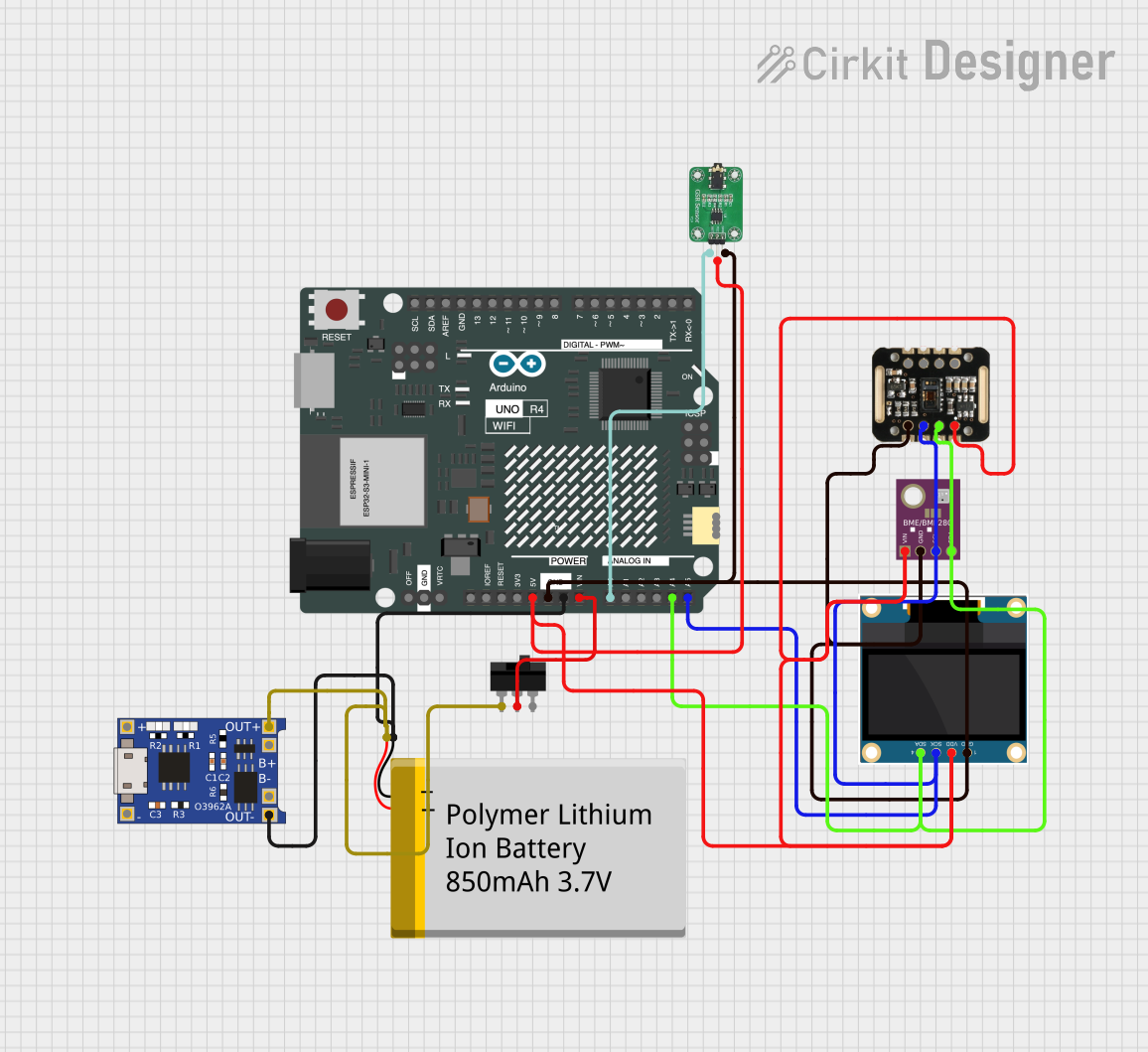
Circuit Documentation
Summary
This circuit is designed to incorporate a variety of sensors and modules to create a health monitoring device. It features an Arduino UNO R4 WiFi as the central microcontroller, interfacing with a BME/BMP280 for environmental sensing, a MAX30100 for pulse oximetry, a 0.96" OLED display for output, and a GSR sensor for galvanic skin response measurements. Power management is handled by a TP4056 charging module and a Polymer Lithium Ion Battery. A toggle switch is included for power control.
Component List
Arduino UNO R4 WiFi
- Microcontroller board with WiFi capability.
- Provides I/O pins for interfacing with various sensors and modules.
BME/BMP280
- Environmental sensor for measuring temperature, barometric pressure, and altitude.
- Interfaces with the Arduino via I2C.
MAX30100
- Pulse oximetry and heart-rate sensor.
- Measures the oxygen saturation in the blood and heart rate.
0.96" OLED
- Small display for visual output.
- Communicates with the Arduino over I2C.
TP4056
- Lithium Ion battery charger module.
- Manages charging and power distribution.
Polymer Lithium Ion Battery - 850mAh
- Provides power to the circuit.
- Rechargeable via the TP4056 module.
Toggle Switch
- Allows manual power control of the device.
- Can disconnect or connect the battery to the circuit.
GSR SENSOR
- Measures the electrical conductance of the skin, which varies with its moisture level.
Wiring Details
Arduino UNO R4 WiFi
5Vconnected to OLED VDD, BME/BMP280 VIN, MAX30100 VIN, GSR SENSOR VCC.GNDconnected to OLED GND, BME/BMP280 GND, MAX30100 GND, GSR SENSOR GND, TP4056 OUT-, Polymer Lithium Ion Battery GND.VINconnected to Toggle Switch COM.A0connected to GSR SENSOR OUT.A4(SDA) connected to OLED SDA, BME/BMP280 SDA, MAX30100 SDA.A5(SCL) connected to OLED SCK, BME/BMP280 SCL, MAX30100 SCL.
BME/BMP280
GNDconnected to Arduino GND.SCLconnected to Arduino A5.SDAconnected to Arduino A4.VINconnected to Arduino 5V.
MAX30100
GNDconnected to Arduino GND.SCLconnected to Arduino A5.SDAconnected to Arduino A4.VINconnected to Arduino 5V.
0.96" OLED
GNDconnected to Arduino GND.VDDconnected to Arduino 5V.SCKconnected to Arduino A5.SDAconnected to Arduino A4.
TP4056
OUT-connected to Arduino GND.OUT+connected to Toggle Switch L1.
Polymer Lithium Ion Battery - 850mAh
GNDconnected to TP4056 OUT-.VCCconnected to Toggle Switch L1.
Toggle Switch
COMconnected to Arduino VIN.L1connected to TP4056 OUT+ and Polymer Lithium Ion Battery VCC.
GSR SENSOR
GNDconnected to Arduino GND.VCCconnected to Arduino 5V.OUTconnected to Arduino A0.
Documented Code
Arduino UNO R4 WiFi Code
// libraries needed!

#include <WiFi.h>                //wifi library
// #include <BlynkSimpleEsp32.h>    // blynk library
#include <Adafruit_GFX.h>        // OLED Library
#include <Adafruit_SSD1306.h>    // OLED Library
#include <Wire.h>                // I2C  Library
#include <Adafruit_Sensor.h>
#include <Adafruit_BME280.h>
#include "MAX30105.h"            // MAX3010x library
#include "heartRate.h"           // Heart rate calculating algorithm

// #define BLYNK_PRINT Serial
// WiFiClient  client;

// BlynkTimer timer;

// char authBlynk[] = "9dXleInVrfDzCKLMk8RS7UuhWJAXZ2pU";
// char ssid[] = "HOME Wifi";
// char pass[] = "12345678";

Adafruit_BME280 bme;
MAX30105 particleSensor;

const byte RATE_SIZE = 4;        // Increase this for more averaging. 4 is good.
byte rates[RATE_SIZE];           // Array of heart rates
byte rateSpot = 0;
long lastBeat = 0;               // Time at which the last beat occurred
float beatsPerMinute;
int beatAvg;

#define SCREEN_WIDTH 128         // OLED display width, in pixels
#define SCREEN_HEIGHT 64         // OLED display height, in pixels
#define OLED_RESET    -1         // Reset pin # (or -1 if sharing Arduino reset pin)

Adafruit_SSD1306 display(SCREEN_WIDTH, SCREEN_HEIGHT, &Wire, OLED_RESET); //Declaring the display name (display)

void setup() {
  bool status = bme.begin(0x76);
  if (!status) {
    Serial.println("Could not find a valid BME280 sensor, check wiring!");
    while (1);
  }
  Serial.begin(115200);
  Serial.println("BIO WATCH DEVICE...");
  Wire.setClock(400000);                         // Set I2C speed to 400kHz
  display.begin(SSD1306_SWITCHCAPVCC, 0x3C);     // Start the OLED display
  display.setTextColor(WHITE);

  // Initialize sensor
  particleSensor.begin(Wire, I2C_SPEED_FAST);    // Use default I2C port, 400kHz speed
  particleSensor.setup();                        // Configure sensor with default settings
  particleSensor.setPulseAmplitudeRed(0x0A);     // Turn Red LED to low to indicate sensor is running

  display.clearDisplay();
  display.setTextSize(2);
  display.setCursor(0, 0);
  display.print("BHD!");
  display.display();
  // Blynk.begin(authBlynk, ssid, pass);
  // delay (3000);

}

void loop() {
  long irValue = particleSensor.getIR();              // Reading the IR value it will permit us to know if there's a finger on the sensor or not

  //  Blynk.run();

  if (irValue > 50000)
  {

    if (checkForBeat(irValue) == true)                  //If a heart beat is detected, call checkForBeat as frequent as possible to get accurate value
    {
      long delta = millis() - lastBeat;                 //Measure duration between two beats
      lastBeat = millis();
      beatsPerMinute = 60 / (delta / 1000.0);           //Calculating the BPM
      if (beatsPerMinute < 255 and beatsPerMinute > 20)  //To calculate the average we strore some values (4) then do some math to calculate the average
      {
        rates[rateSpot++] = (byte)beatsPerMinute;       //Store this reading in the array
        rateSpot %= RATE_SIZE;                          //Wrap variable

        //Take average of readings
        beatAvg = 0;
        for (byte x = 0 ; x < RATE_SIZE ; x++)
          beatAvg += rates[x];
        beatAvg /= RATE_SIZE;

        display.clearDisplay();
        display.setTextSize(2);
        display.setCursor(0, 5);
        display.print("TEMP:");
        display.print(String(bme.readTemperature()));
        display.print("C");
        display.setTextSize(3);
        display.setCursor(0, 25);
        display.print("BPM:");
        display.print(beatAvg);
        display.setTextSize(1);
        display.print("BPM");
        display.display();
        // Blynk.virtualWrite(V0, temperature);
        // Blynk.virtualWrite(V1,beatAvg );
      }
    }
  }
  else
  {
    display.clearDisplay();
    display.setTextSize(3);
    display.setCursor(0, 20);
    display.print("BPM:");
    display.print(0);
    display.setCursor(0, 45);
    display.setTextSize(1);
    display.print("Place your finger in sensor and wait..");
    display.display();
    // Blynk.virtualWrite(V0, 0);
    // Blynk.virtualWrite(V1,0 );
  }
}
This code is responsible for initializing the sensors and display, reading sensor data, calculating the heart rate, displaying the temperature and heart rate on the OLED screen, and handling the I2C communication. The Blynk-related code is commented out, indicating that it is not currently used in this implementation.