
Arduino Nano Controlled Line Follower Robot with L298N Motor Driver and IR Sensors
View and Edit Project In Cirkit Designer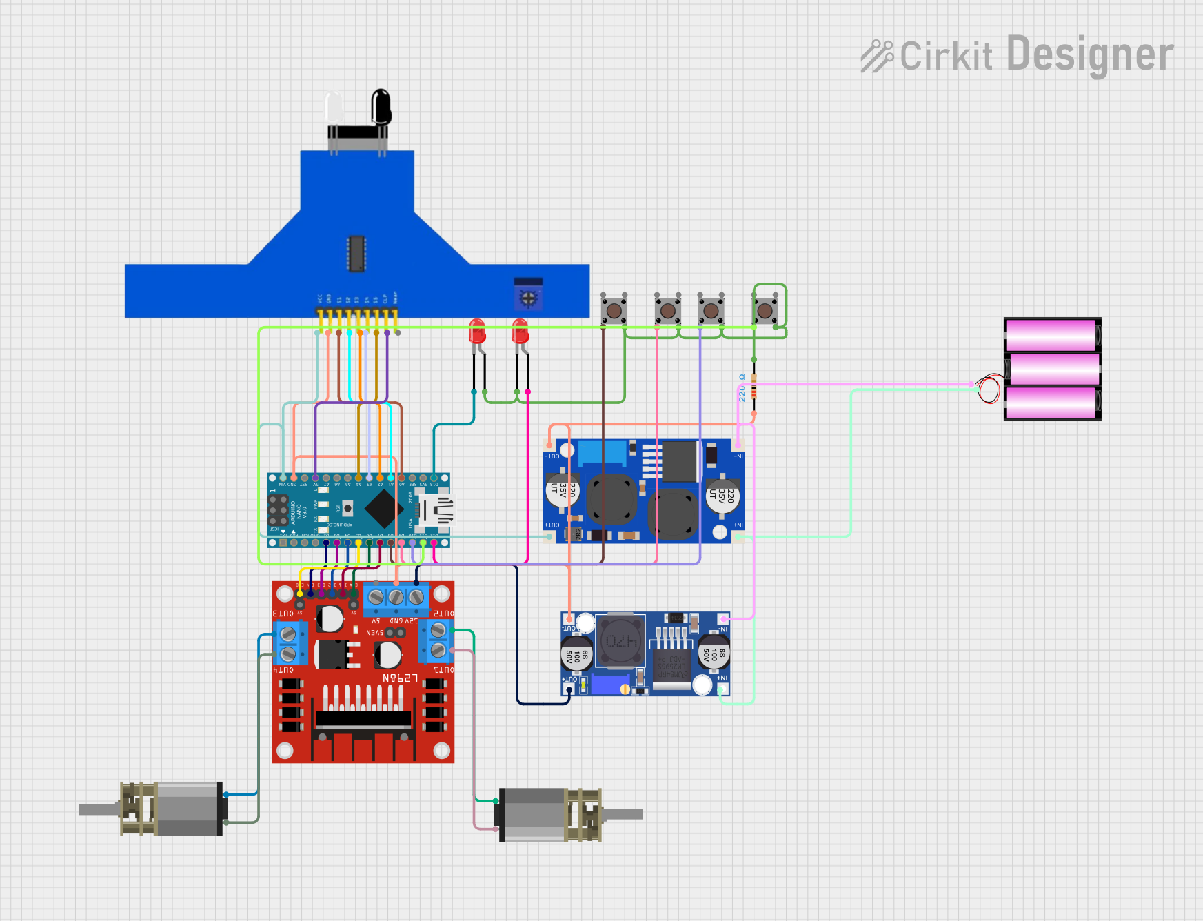
Circuit Documentation
Summary
This circuit is designed to control a line follower robot using an Arduino Nano as the central processing unit. The robot is equipped with an L298N DC motor driver to control two DC Mini Metal Gear Motors, a 5-channel IR sensor for line tracking, and multiple pushbuttons and LEDs for user interaction and status indication. The circuit also includes a buck converter and a boost converter to manage power distribution, and it is powered by a 12V battery. The Arduino Nano is programmed to handle sensor inputs, motor control, and user inputs to navigate the robot along a predefined path.
Component List
Arduino Nano
A compact microcontroller board based on the ATmega328P, featuring digital and analog I/O pins, which serves as the brain of the robot.
L298N DC Motor Driver
A module capable of driving two DC motors with direction and speed control, used for actuating the robot's wheels.
Buck Converter
A DC-DC converter that steps down voltage from a higher level to a lower level, ensuring that the components receive the appropriate voltage.
XL6009E1 Boost Converter
A DC-DC converter that steps up voltage from a lower level to a higher level, used to increase voltage when necessary.
DC Mini Metal Gear Motor (x2)
Small DC motors with gear reduction, providing the necessary torque and speed for the robot's movement.
LED: Two Pin (red) (x2)
Simple red LEDs used for status indication on the robot.
Pushbutton (x4)
Tactile switches used to change modes and control the robot manually.
Resistor
A 220 Ohm resistor used to limit current to the LEDs, protecting them from damage due to overcurrent.
5 Channel IR Sensor
An array of infrared sensors used to detect the line on the surface and provide feedback for the line following algorithm.
Battery 12V
A 12V battery that provides power to the entire circuit.
Wiring Details
Arduino Nano
- D2 to L298N DC motor driver IN4
- D3 to L298N DC motor driver IN3
- D4 to L298N DC motor driver IN2
- D5 to L298N DC motor driver ENB
- D6 to L298N DC motor driver ENA
- D7 to L298N DC motor driver IN1
- D8 to Pushbutton Pin 2 (in)
- D9 to Pushbutton Pin 2 (in)
- D10 to Pushbutton Pin 2 (in)
- D11/MOSI to Pushbutton Pin 2 (in)
- D12/MISO to LED (red) anode
- VIN to 5 channel IR sensor VCC and XL6009E1 Boost Converter OUT+
- GND to Buck converter OUT-, Resistor pin1, 5 channel IR sensor GND, L298N DC motor driver GND, XL6009E1 Boost Converter OUT-
- 5V to 5 channel IR sensor CLP
- A4 to 5 channel IR sensor S5
- A3 to 5 channel IR sensor S4
- A2 to 5 channel IR sensor S3
- A1 to 5 channel IR sensor S2
- A0 to 5 channel IR sensor S1
- D13/SCK to LED (red) cathode
L298N DC Motor Driver
- OUT1 to DC Mini Metal Gear Motor IN2
- OUT2 to DC Mini Metal Gear Motor IN1
- OUT3 to DC Mini Metal Gear Motor IN2
- OUT4 to DC Mini Metal Gear Motor IN1
- 12V to Buck converter OUT+
Buck Converter
- IN+ to XL6009E1 Boost Converter IN+ and Battery 12V +
- IN- to XL6009E1 Boost Converter IN- and Battery 12V -
XL6009E1 Boost Converter
- OUT+ to Arduino Nano VIN
- OUT- to Arduino Nano GND
DC Mini Metal Gear Motor
- No additional wiring details beyond connections to the L298N DC motor driver.
LED: Two Pin (red)
- Anode to Arduino Nano D12/MISO
- Cathode to Arduino Nano D13/SCK and Pushbutton Pin 4 (out) through a 220 Ohm resistor
Pushbutton
- Pin 2 (in) to Arduino Nano D8, D9, D10, D11/MOSI
- Pin 4 (out) to LED (red) cathode through a 220 Ohm resistor
Resistor
- Pin1 to Arduino Nano GND
- Pin2 to LED (red) cathode and Pushbutton Pin 4 (out)
5 Channel IR Sensor
- VCC to Arduino Nano VIN
- GND to Arduino Nano GND
- S1 to Arduino Nano A0
- S2 to Arduino Nano A1
- S3 to Arduino Nano A2
- S4 to Arduino Nano A3
- S5 to Arduino Nano A4
- CLP to Arduino Nano 5V
Battery 12V
-
- to Buck converter IN+ and XL6009E1 Boost Converter IN+
-
- to Buck converter IN- and XL6009E1 Boost Converter IN-
Documented Code
/*
 * Arduino Sketch for Line Follower Robot
 * This code controls a line follower robot using an Arduino Nano, L298N motor driver,
 * and IR sensors. The robot follows a line based on sensor readings and uses PID
 * control for smooth movement. It also includes pushbutton controls for different
 * modes and LED indicators.
 */

// Motor pin defines
#define rmf 4 // IN1
#define rmb 7 // IN2
#define lmf 3 // IN3
#define lmb 2 // IN4
#define rms 6 // ENA
#define lms 5 // ENB

// Pushbutton and LED pin defines
int button1 = 8;
int button2 = 9;
int button3 = 10;
int button4 = 11;
int led12 = 12;
int led13 = 13;
bool button1_state, button2_state, button3_state, button4_state;

// Line follower variables
int s[6], sum;
int position[6] = {1, 2, 3, 4, 5, 6};
int threshold = 512, sensor;
int lbase = 200, rbase = 200;
int lmotor, rmotor;
float avg;
int kp = 50, kd = 1000;
int PID;
float error, last_error;
char turn;
int base[6] = {1, 2, 4, 8, 16, 32};
int tsp = 100;

void setup() {
  // Motor driver pins as output
  pinMode(lmf, OUTPUT);
  pinMode(lmb, OUTPUT);
  pinMode(rmf, OUTPUT);
  pinMode(rmb, OUTPUT);
  pinMode(rms, OUTPUT);
  pinMode(lms, OUTPUT);

  // Button pins as input with pull-up resistors
  pinMode(button1, INPUT_PULLUP);
  pinMode(button2, INPUT_PULLUP);
  pinMode(button3, INPUT_PULLUP);
  pinMode(button4, INPUT_PULLUP);

  // LED pins as output
  pinMode(led12, OUTPUT);
  pinMode(led13, OUTPUT);

  Serial.begin(9600);
}

void loop() {
  digitalWrite(led13, HIGH);
  button_status();

  // Line following mode
  while (button1_state != 1) {
    digitalWrite(led13, LOW);
    for (int i = 0; i < 5; i++) {
      digitalWrite(led12, HIGH);
      delay(100);
      digitalWrite(led12, LOW);
      delay(100);
    }
    PID_LINE_FOLLOW();
  }

  // Motor test mode
  while (button2_state != 1) {
    digitalWrite(led13, LOW);
    for (int i = 0; i < 3; i++) {
      digitalWrite(led12, HIGH);
      delay(500);
      digitalWrite(led12, LOW);
      delay(500);
    }
    motor(250, 250);
    delay(3000);
    motor(0, 0);
    button_status();
  }

  // Sensor test mode
  while (button3_state != 1) {
    digitalWrite(led13, LOW);
    for (short int i = 0; i <= 5; i++) {
      Serial.print(String(analogRead(i)) + " ");
    }
    Serial.println();
    digitalWrite(led12, HIGH);
    delay(50);
    digitalWrite(led12, LOW);
    delay(50);
  }

  // Stop mode
  while (button4_state != 1) {
    motor(0, 0);
    digitalWrite(led13, HIGH);
    button_status();
  }
}

void button_status() {
  button1_state = digitalRead(button1);
  button2_state = digitalRead(button2);
  button3_state = digitalRead(button3);
  button4_state = digitalRead(button4);
}

void PID_LINE_FOLLOW() {
  sensor = 0;
  sum = 0;
  for (byte i = 0; i < 6; i++) {
    s[i] = analogRead(i);
    s[i] = (s[i] > threshold) ? 1 : 0;
    sum += s[i] * position[i];
  }