
ESP32-Controlled Robot with Triple Ultrasonic Sensors and L298N Motor Driver
View and Edit Project In Cirkit Designer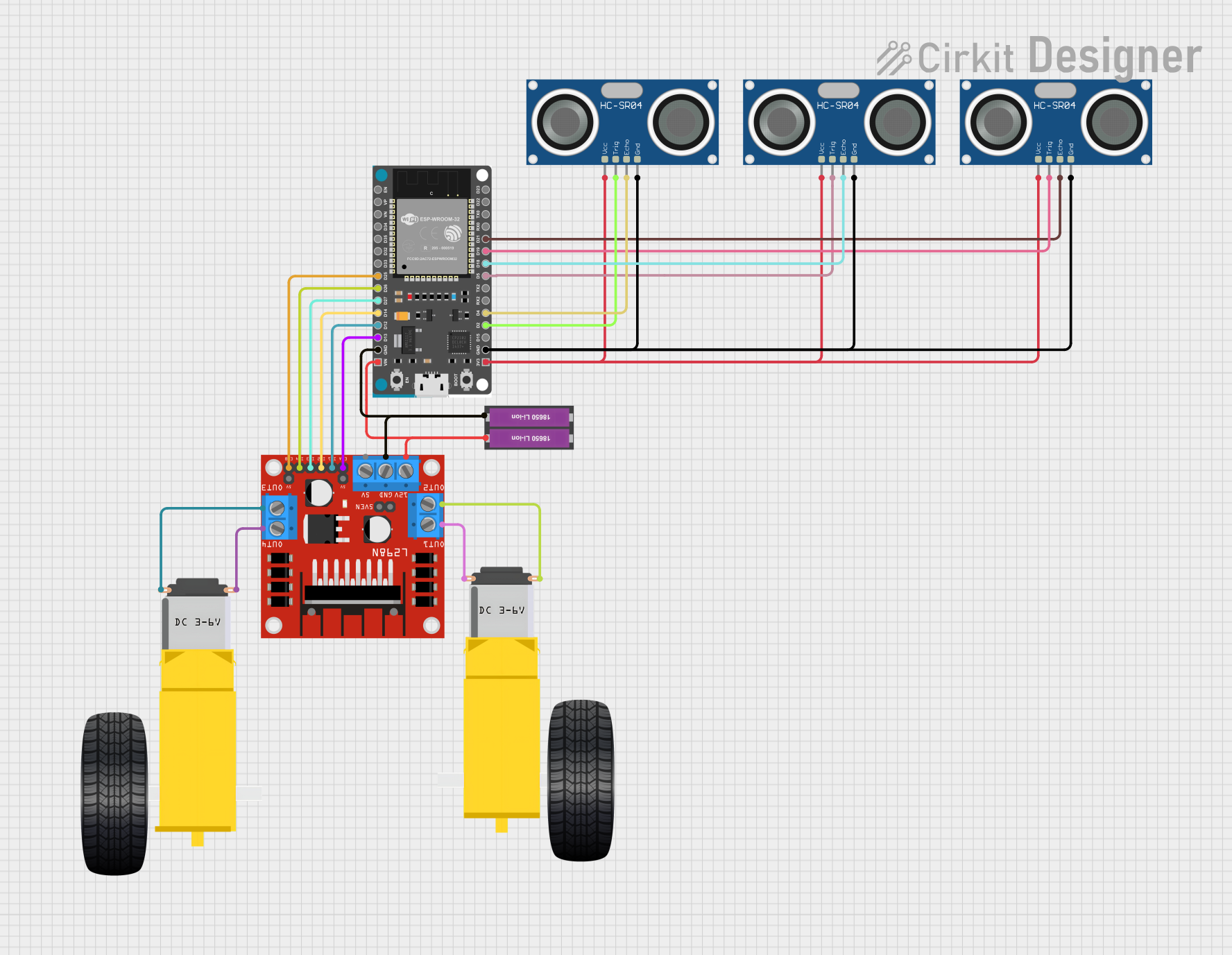
Circuit Documentation
Summary
The circuit in question appears to be designed for a mobile robot or a similar automated system. It includes ultrasonic sensors for distance measurement, a microcontroller for processing and control, a motor driver for actuating DC motors, and a power source. The ESP32 Devkit V1 microcontroller serves as the central processing unit, interfacing with the HC-SR04 ultrasonic sensors and controlling the L298N DC motor driver, which in turn drives the gearmotors for the wheels.
Component List
HC-SR04 Ultrasonic Sensor
- Description: An ultrasonic distance sensor that uses sonar to determine the distance to an object.
- Pins: VCC, TRIG, ECHO, GND
L298N DC Motor Driver
- Description: A high-power motor driver capable of driving DC motors with a supply voltage up to 46V.
- Pins: OUT1, OUT2, 12V, GND, 5V, OUT3, OUT4, 5V-ENA-JMP-I, 5V-ENA-JMP-O, +5V-J1, +5V-J2, ENA, IN1, IN2, IN3, IN4, ENB
Gearmotor DC Wheels (Left and Right)
- Description: DC gearmotors used to drive the wheels of the robot.
- Pins: PIN1, PIN2
ESP32 Devkit V1
- Description: A microcontroller with Wi-Fi and Bluetooth capabilities, suitable for a wide range of applications and power performance scenarios.
- Pins: 3V3, GND, D15, D2, D4, RX2, TX2, D5, D18, D19, D21, RX0, TX0, D22, D23, EN, VP, VN, D34, D35, D32, D33, D25, D26, D27, D14, D12, D13, VIN
18650 Li-ion Battery x 2
- Description: A power source for the circuit, consisting of two 18650 lithium-ion batteries.
- Pins: +, -
Wiring Details
HC-SR04 Ultrasonic Sensors
- VCC: Connected to the 3V3 pin of the ESP32 Devkit V1.
- TRIG: Each sensor's TRIG pin is connected to a designated GPIO pin on the ESP32 Devkit V1 (D5, D2, D19).
- ECHO: Each sensor's ECHO pin is connected to a designated GPIO pin on the ESP32 Devkit V1 (D18, D4, D21).
- GND: Connected to the GND pin of the ESP32 Devkit V1.
L298N DC Motor Driver
- OUT1, OUT2: Connected to the Gearmotor DC Wheels Right.
- OUT3, OUT4: Connected to the Gearmotor DC Wheels Left.
- 12V: Connected to the + pin of the 18650 Li-ion Battery x 2.
- GND: Connected to the GND pin of the ESP32 Devkit V1 and the - pin of the 18650 Li-ion Battery x 2.
- ENA, ENB: Connected to designated GPIO pins on the ESP32 Devkit V1 (D13, D25).
- IN1, IN2, IN3, IN4: Connected to designated GPIO pins on the ESP32 Devkit V1 (D12, D14, D27, D26).
Gearmotor DC Wheels (Left and Right)
- PIN1, PIN2: Each gearmotor's pins are connected to the corresponding OUT pins on the L298N DC motor driver.
ESP32 Devkit V1
- 3V3: Provides power to the VCC pins of the HC-SR04 Ultrasonic Sensors.
- GND: Common ground for the circuit.
- VIN: Connected to the + pin of the 18650 Li-ion Battery x 2.
- GPIO Pins (D5, D2, D4, D18, D19, D21, D25, D26, D27, D14, D12, D13): Used for interfacing with the HC-SR04 Ultrasonic Sensors and controlling the L298N DC motor driver.
18650 Li-ion Battery x 2
- +: Provides power to the VIN pin of the ESP32 Devkit V1 and the 12V pin of the L298N DC motor driver.
- -: Common ground for the circuit.
Documented Code
Since no code was provided in the input, this section cannot be completed. Normally, this section would include the embedded code for the microcontroller, with comments explaining the functionality and the logic behind the code. It would detail how the microcontroller interfaces with the sensors and the motor driver, as well as any algorithms used for processing sensor data or controlling the motors.