
ESP32-CAM Ultrasonic Distance Measurement with OLED Display and Servo Control
View and Edit Project In Cirkit Designer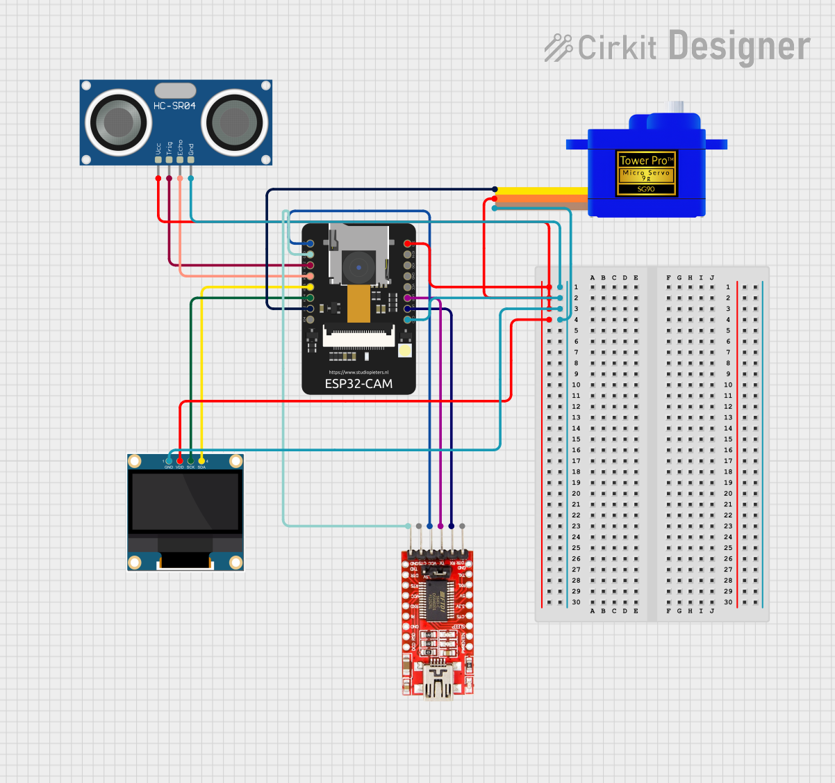
Circuit Documentation
Summary
This circuit is an ESP32-CAM based system designed for ultrasonic distance measurement, OLED display output, and servo motor control. The ESP32-CAM reads distance data from an HC-SR04 ultrasonic sensor, displays the distance on a 0.96" OLED display, and controls a servo motor based on the measured distance. An FTDI programmer is used for programming the ESP32-CAM.
Component List
ESP32-CAM
- Description: A microcontroller with integrated Wi-Fi and Bluetooth, equipped with a camera module.
- Pins: 5V, GND, IO12, IO13, IO15, IO14, IO2, IO4, VOT, VOR, VCC, IO0, IO16, 3V3
FTDI Programmer
- Description: A USB-to-serial adapter used for programming the ESP32-CAM.
- Pins: DTR, RX, TX, VCC, CTS, GND
0.96" OLED
- Description: A small OLED display used to show distance measurements.
- Pins: GND, VDD, SCK, SDA
HC-SR04 Ultrasonic Sensor
- Description: An ultrasonic sensor used to measure distance.
- Pins: VCC, TRIG, ECHO, GND
Servomotor SG90
- Description: A small servo motor used for physical movement based on distance measurements.
- Pins: SIG, VCC, GND
Wiring Details
ESP32-CAM
- 3V3: Connected to VCC of Servomotor SG90, VCC of HC-SR04 Ultrasonic Sensor, and VDD of 0.96" OLED
- GND: Connected to GND of HC-SR04 Ultrasonic Sensor, GND of 0.96" OLED, and GND of Servomotor SG90
- 5V: Connected to VCC of FTDI Programmer
- IO12: Connected to TRIG of HC-SR04 Ultrasonic Sensor
- IO13: Connected to ECHO of HC-SR04 Ultrasonic Sensor
- IO15: Connected to SDA of 0.96" OLED
- IO14: Connected to SCK of 0.96" OLED
- IO2: Connected to SIG of Servomotor SG90
- VOT: Connected to RX of FTDI Programmer
- VOR: Connected to TX of FTDI Programmer
FTDI Programmer
- VCC: Connected to 5V of ESP32-CAM
- GND: Connected to GND of ESP32-CAM
- RX: Connected to VOT of ESP32-CAM
- TX: Connected to VOR of ESP32-CAM
0.96" OLED
- GND: Connected to GND of ESP32-CAM
- VDD: Connected to 3V3 of ESP32-CAM
- SCK: Connected to IO14 of ESP32-CAM
- SDA: Connected to IO15 of ESP32-CAM
HC-SR04 Ultrasonic Sensor
- VCC: Connected to 3V3 of ESP32-CAM
- GND: Connected to GND of ESP32-CAM
- TRIG: Connected to IO12 of ESP32-CAM
- ECHO: Connected to IO13 of ESP32-CAM
Servomotor SG90
- SIG: Connected to IO2 of ESP32-CAM
- VCC: Connected to 3V3 of ESP32-CAM
- GND: Connected to GND of ESP32-CAM
Code Documentation
/*
 * ESP32-CAM Based Ultrasonic Distance Measurement with OLED Display and Servo Control
 *
 * This code reads distance data from an HC-SR04 ultrasonic sensor, displays the
 * distance on a 0.96" OLED display, and controls a servo motor based on the
 * measured distance. The ESP32-CAM is used as the main microcontroller.
 */

#include <Wire.h>
#include <Adafruit_GFX.h>
#include <Adafruit_SSD1306.h>
#include <Servo.h>

#define TRIG_PIN 12
#define ECHO_PIN 13
#define SERVO_PIN 2
#define SCREEN_WIDTH 128
#define SCREEN_HEIGHT 64

Adafruit_SSD1306 display(SCREEN_WIDTH, SCREEN_HEIGHT, &Wire, -1);
Servo myServo;

void setup() {
  Serial.begin(115200);
  pinMode(TRIG_PIN, OUTPUT);
  pinMode(ECHO_PIN, INPUT);
  myServo.attach(SERVO_PIN);
  if(!display.begin(SSD1306_I2C_ADDRESS, 0x3C)) {
    Serial.println(F("SSD1306 allocation failed"));
    for(;;);
  }
  display.clearDisplay();
  display.setTextSize(1);
  display.setTextColor(SSD1306_WHITE);
  display.setCursor(0, 0);
  display.print("Distance:");
  display.display();
}

void loop() {
  long duration, distance;
  digitalWrite(TRIG_PIN, LOW);
  delayMicroseconds(2);
  digitalWrite(TRIG_PIN, HIGH);
  delayMicroseconds(10);
  digitalWrite(TRIG_PIN, LOW);
  duration = pulseIn(ECHO_PIN, HIGH);
  distance = (duration / 2) / 29.1;
  display.setCursor(0, 10);
  display.clearDisplay();
  display.setTextSize(2);
  display.print(distance);
  display.print(" cm");
  display.display();
  if (distance < 10) {
    myServo.write(0);
  } else if (distance < 20) {
    myServo.write(90);
  } else {
    myServo.write(180);
  }
  delay(500);
}
This code initializes the necessary components, reads distance data from the HC-SR04 ultrasonic sensor, displays the distance on the OLED, and controls the servo motor based on the measured distance.