Cirkit Designer
Your all-in-one circuit design IDE
Home /
Project Documentation
Motion-Activated Sound Player with Arduino and MPU6050

Circuit Documentation
Summary
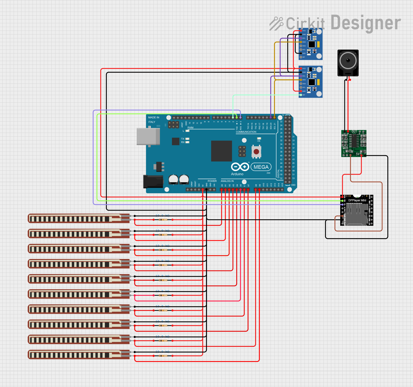
This circuit integrates an Arduino Mega 2560 with multiple sensors and modules to perform various functions. The Arduino Mega 2560 serves as the central processing unit, interfacing with MPU6050 Accelerometer + Gyroscope modules for motion sensing, DFPlayer MINI for audio playback, and PAM8403 audio amplifier for driving a loudspeaker. The circuit also includes several 2.2 inch Basic Flex Resistors and standard resistors for voltage division and current limiting purposes.
Component List
Microcontroller
- Arduino Mega 2560: A microcontroller board based on the ATmega2560, with numerous digital and analog I/O pins.
Sensors
- MPU6050 Accelerometer + Gyroscope (Wokwi Compatible): Motion tracking devices that provide 6 degrees of freedom, measuring both acceleration and rotational changes.
Audio Components
- DFPlayer MINI: A small and low-cost MP3 module that can directly play MP3 files from a USB drive or from a micro SD card.
- PAM8403: A digital audio amplifier capable of driving a stereo pair of speakers.
- Loudspeaker: An electroacoustic transducer used to produce sound.
Resistive Components
- 2.2 inch Basic Flex Resistor: A flexible resistor whose resistance changes when bent.
- Resistor (10k Ohms): A standard resistor with a resistance of 10,000 Ohms, used for various purposes such as pull-ups or voltage dividers.
Wiring Details
Arduino Mega 2560
- 5V and GND pins are used to power the circuit.
- Analog pins A0-A9 are connected to flex resistors and 10k Ohm resistors for analog input.
- Digital pins D0 (RX0) and D1 (TX0) are used for serial communication with the DFPlayer MINI.
- Digital pin D2 (PWM) is connected to the interrupt pin of one MPU6050 module.
- I2C pins D20 (SDA) and D21 (SCL) are connected to the SDA and SCL pins of both MPU6050 modules for communication.
MPU6050 Accelerometer + Gyroscope (Wokwi Compatible)
- VCC and GND pins are connected to the power supply lines.
- SDA and SCL pins are connected to the I2C bus of the Arduino Mega 2560.
- INT pin of one MPU6050 is connected to digital pin D2 (PWM) on the Arduino Mega 2560 for interrupt-driven events.
- AD0 pin is used to set the I2C address of the MPU6050 modules.
DFPlayer MINI
- VCC and GND pins are connected to the power supply lines.
- RX and TX pins are connected to the TX0 and RX0 pins of the Arduino Mega 2560 for serial communication.
- SPK1 pin is connected to the R-INPUT of the PAM8403 amplifier.
PAM8403
- 5vIN+ and GND/IN- pins are connected to the power supply lines.
- R-INPUT is connected to the SPK1 pin of the DFPlayer MINI.
- L- and L+ pins are connected to the pins of the Loudspeaker.
Loudspeaker
- Connected to the L- and L+ pins of the PAM8403 amplifier.
2.2 inch Basic Flex Resistor
- One pin is connected to the GND, and the other pin is connected to the analog input pins of the Arduino Mega 2560.
Resistor (10k Ohms)
- One pin is connected to the 5V power supply, and the other pin is connected to the analog input pins of the Arduino Mega 2560.
Documented Code
Arduino Mega 2560 Code (sketch.ino)
void setup() {
  // put your setup code here, to run once:

}

void loop() {
  // put your main code here, to run repeatedly:

}
Note: The provided code is a template and does not include specific functionality. It needs to be populated with the logic to interact with the connected components based on the requirements of the circuit's application.