
Arduino and ESP32-Based Smart Home Automation System with Sensor Integration
View and Edit Project In Cirkit Designer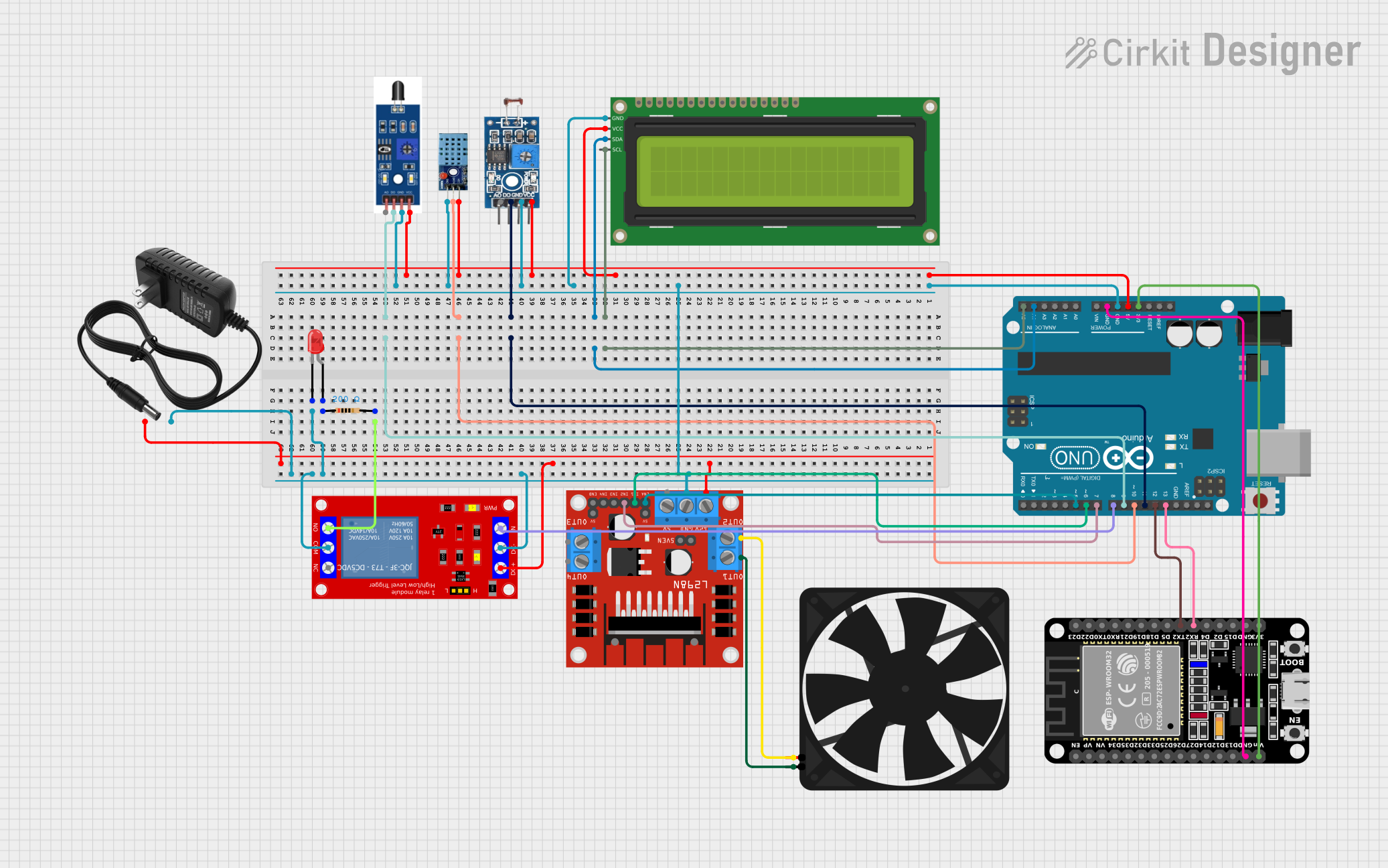
Circuit Documentation
Summary
This circuit integrates an Arduino UNO, an ESP32, various sensors, a relay module, an LCD display, a motor driver, and other components to create a comprehensive system. The Arduino UNO serves as the primary microcontroller, interfacing with sensors and actuators, while the ESP32 provides additional processing power and connectivity. The system includes a light sensor, temperature and humidity sensor, flame sensor, relay module, LCD display, and a fan controlled by a motor driver.
Component List
Arduino UNO
- Description: A microcontroller board based on the ATmega328P.
- Pins: UNUSED, IOREF, Reset, 3.3V, 5V, GND, Vin, A0, A1, A2, A3, A4, A5, SCL, SDA, AREF, D13, D12, D11, D10, D9, D8, D7, D6, D5, D4, D3, D2, D1, D0
1 Channel 5V Relay Module
- Description: A relay module used to control high voltage devices.
- Pins: VCC+, VCC- (GND), IN, N.O., COM, N.C.
16x2 I2C LCD
- Description: A 16x2 character LCD display with I2C interface.
- Pins: GND, VCC, SDA, SCL
ESP32 (30 pin)
- Description: A low-cost, low-power system on a chip microcontroller with integrated Wi-Fi and dual-mode Bluetooth.
- Pins: EN, VP, VN, D34, D35, D32, D33, D25, D26, D27, D14, D12, D13, GND, Vin, D23, D22, TX0, RX0, D21, D19, D18, D5, TX2, RX2, D4, D2, D15, 3V3
Photosensitive Sensor Module Digital Light Intensity Detection
- Description: A sensor module used to detect light intensity.
- Pins: Analog Output, Digital Output, Ground, VCC
DHT 11
- Description: A temperature and humidity sensor.
- Pins: VCC, GND, DATA
Flame Sensor
- Description: A sensor used to detect flame or fire.
- Pins: A0, GND, D0, VCC
Resistor
- Description: A 200 Ohms resistor.
- Pins: pin1, pin2
12v Power Supply
- Description: A power supply providing 12V.
- Pins: +, -
LED: Two Pin (red)
- Description: A red LED.
- Pins: cathode, anode
Fan
- Description: A fan used for cooling.
- Pins: GND, 5V
L298N DC Motor Driver
- Description: A dual H-Bridge motor driver.
- Pins: OUT1, OUT2, 12V, GND, 5V, OUT3, OUT4, 5V-ENA-JMP-I, 5V-ENA-JMP-O, +5V-J1, +5V-J2, ENA, IN1, IN2, IN3, IN4, ENB
Wiring Details
Arduino UNO
- 3.3V connected to ESP32 Vin
- 5V connected to 16x2 I2C LCD VCC, Photosensitive Sensor Module VCC, DHT 11 VCC, Flame Sensor VCC
- GND connected to 16x2 I2C LCD GND, Photosensitive Sensor Module Ground, DHT 11 GND, Flame Sensor GND, L298N DC Motor Driver GND, 1 Channel 5V Relay Module VCC- (GND), 1 Channel 5V Relay Module COM, 12v Power Supply -, LED cathode, ESP32 GND
- A4 connected to 16x2 I2C LCD SDA
- A5 connected to 16x2 I2C LCD SCL
- D13 connected to ESP32 RX2
- D12 connected to ESP32 TX2
- D11 connected to Photosensitive Sensor Module Digital Output
- D10 connected to DHT 11 DATA
- D9 connected to Flame Sensor D0
- D8 connected to 1 Channel 5V Relay Module IN
- D7 connected to L298N DC Motor Driver IN2
- D6 connected to L298N DC Motor Driver IN1
- D5 connected to L298N DC Motor Driver ENA
1 Channel 5V Relay Module
- VCC+ connected to 12v Power Supply +, L298N DC Motor Driver 12V
- N.O. connected to Resistor pin2
16x2 I2C LCD
- VCC connected to Arduino UNO 5V
- GND connected to Arduino UNO GND
- SDA connected to Arduino UNO A4
- SCL connected to Arduino UNO A5
ESP32 (30 pin)
- Vin connected to Arduino UNO 3.3V
- GND connected to Arduino UNO GND
- RX2 connected to Arduino UNO D13
- TX2 connected to Arduino UNO D12
Photosensitive Sensor Module Digital Light Intensity Detection
- VCC connected to Arduino UNO 5V
- Ground connected to Arduino UNO GND
- Digital Output connected to Arduino UNO D11
DHT 11
- VCC connected to Arduino UNO 5V
- GND connected to Arduino UNO GND
- DATA connected to Arduino UNO D10
Flame Sensor
- VCC connected to Arduino UNO 5V
- GND connected to Arduino UNO GND
- D0 connected to Arduino UNO D9
Resistor
- pin1 connected to LED anode
- pin2 connected to 1 Channel 5V Relay Module N.O.
12v Power Supply
- + connected to 1 Channel 5V Relay Module VCC+, L298N DC Motor Driver 12V
- - connected to Arduino UNO GND
LED: Two Pin (red)
- cathode connected to Arduino UNO GND
- anode connected to Resistor pin1
Fan
- GND connected to L298N DC Motor Driver OUT1
- 5V connected to L298N DC Motor Driver OUT2
L298N DC Motor Driver
- GND connected to Arduino UNO GND
- 12V connected to 12v Power Supply +
- IN2 connected to Arduino UNO D7
- IN1 connected to Arduino UNO D6
- ENA connected to Arduino UNO D5
- OUT1 connected to Fan GND
- OUT2 connected to Fan 5V
Documented Code
Arduino UNO Code (sketch.ino)
void setup() {
  // put your setup code here, to run once:

}

void loop() {
  // put your main code here, to run repeatedly:

}
Additional Documentation (documentation.txt)
This documentation provides a comprehensive overview of the circuit, including a detailed component list, wiring details, and the code used in the microcontroller.