Arduino UNO Based GPS Tracker with SMS Updates
Circuit Documentation
Summary of the Circuit
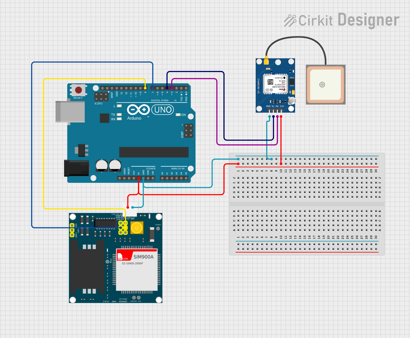
This circuit integrates an Arduino UNO microcontroller with a SIM900A GSM module and a GPS NEO 6M module to create a GPS tracking system that can send location data via SMS. The Arduino UNO serves as the central processing unit, interfacing with the GPS module to receive location coordinates and with the GSM module to send the coordinates as an SMS message. The GPS module provides the location data, while the GSM module enables cellular communication.
Component List
Arduino UNO
- Description: A microcontroller board based on the ATmega328P.
- Pins: UNUSED, IOREF, Reset, 3.3V, 5V, GND, Vin, A0-A5, SCL, SDA, AREF, D0-D13.
SIM900A GSM Module
- Description: A GSM/GPRS module for cellular communication.
- Pins: GND, DB9-3 (RXD), DB9-2 (TXD), 5V, 3VR, 5VR, 3VT, 5VT, VCC, Ring, RESTART, RESET, STATUS.
GPS NEO 6M Module
- Description: A compact GPS module with an integrated antenna.
- Pins: VCC, RX, TX, GND.
Wiring Details
Arduino UNO
- 5V connected to SIM900A 5V and GPS NEO 6M VCC.
- GND connected to SIM900A GND and GPS NEO 6M GND.
- D8 connected to SIM900A 5VR.
- D7 connected to SIM900A 5VT.
- D4 connected to GPS NEO 6M TX.
- D3 connected to GPS NEO 6M RX.
SIM900A GSM Module
- 5V connected to Arduino UNO 5V.
- GND connected to Arduino UNO GND.
- 5VR connected to Arduino UNO D8.
- 5VT connected to Arduino UNO D7.
GPS NEO 6M Module
- VCC connected to Arduino UNO 5V.
- RX connected to Arduino UNO D3.
- TX connected to Arduino UNO D4.
- GND connected to Arduino UNO GND.
Documented Code
#include <TinyGPS++.h>
#include <SoftwareSerial.h>

TinyGPSPlus gps;
SoftwareSerial gpsSerial(4, 3); // GPS Module RX, TX
SoftwareSerial gsmSerial(7, 8); // GSM Module RX, TX

void setup() {
    Serial.begin(9600);
    gpsSerial.begin(9600);
    gsmSerial.begin(9600);
}

void loop() {
    while (gpsSerial.available()) {
        gps.encode(gpsSerial.read());
        if (gps.location.isUpdated()) {
            String latitude = String(gps.location.lat(), 6);
            String longitude = String(gps.location.lng(), 6);
            String locationMessage = "Latitude: " + latitude + ", Longitude: " + longitude;
            Serial.println(locationMessage);
            sendSMS(locationMessage);
            delay(10000);
        }
    }
}

void sendSMS(String message) {
    gsmSerial.print("AT+CMGS=\"+21650751921\"\r");
    delay(1000);
    gsmSerial.print(message);
    delay(1000);
    gsmSerial.write(26); // ASCII code for Ctrl+Z
    delay(1000);
    Serial.println("SMS Sent");
}
Note: The code provided is for the Arduino UNO microcontroller. It initializes two software serial ports for communication with the GPS and GSM modules, reads GPS data, constructs a location message, and sends it via SMS. The phone number in the sendSMS function is hardcoded and should be replaced with the desired recipient's number.