
ESP32-Based Battery-Powered Wi-Fi Temperature Monitoring System with MLX90614 and I2C LCD
View and Edit Project In Cirkit Designer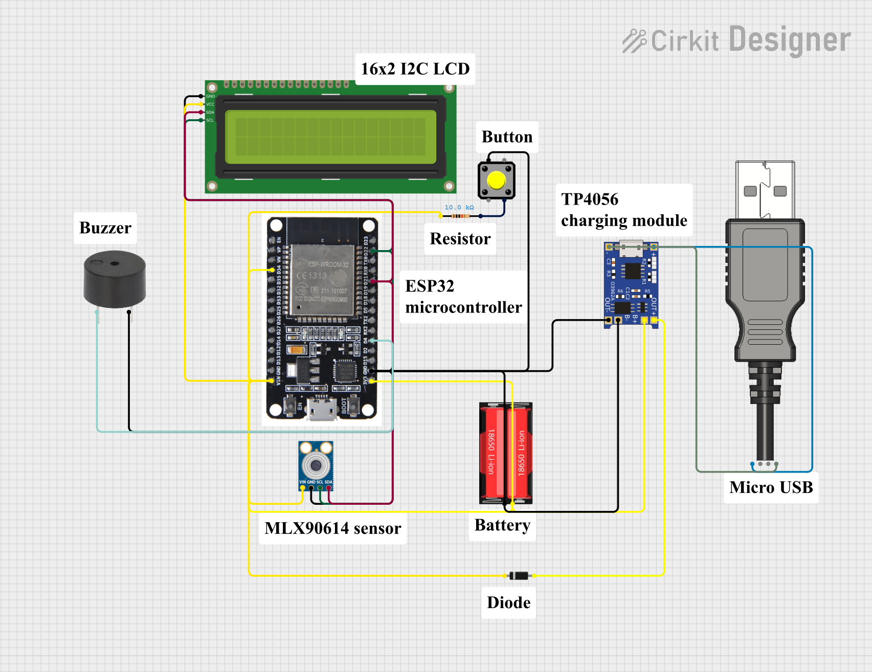
Circuit Documentation
Summary
This circuit is designed to measure temperature using an MLX90614 infrared temperature sensor and display the readings on a 16x2 I2C LCD. The system is powered by a 18650 Li-Ion battery, which is charged using a TP4056 module. An ESP32 microcontroller is used to read the temperature data, send it to a server via Wi-Fi, and manage power consumption. A pushbutton is included to change the mode of temperature measurement, and a buzzer alerts when the battery voltage is low.
Component List
ESP32
- Description: A powerful microcontroller with Wi-Fi and Bluetooth capabilities.
- Pins: EN, VP, VN, D34, D35, D32, D33, D25, D26, D27, D14, D12, D13, GND, VIN, 3V3, D15, D2, D4, RX2, TX2, D5, D18, D19, D21, RX0, TX0, D22, D23, BOOT
MLX90614
- Description: Infrared temperature sensor for non-contact temperature measurements.
- Pins: SDA, SCL, GND, VIN
16x2 I2C LCD
- Description: A 16x2 character LCD with I2C interface for easy communication.
- Pins: GND, VCC, SDA, SCL
TP4056
- Description: Lithium battery charger module with overcharge protection.
- Pins: OUT-, B-, B+, OUT+, IN-, IN+
Pushbutton
- Description: A simple pushbutton for user input.
- Pins: Pin 2, Pin 1, Pin 3, Pin 4
18650 Li-Ion
- Description: Rechargeable lithium-ion battery.
- Pins: Positive, Negative
Resistor
- Description: A resistor with a resistance of 10k Ohms.
- Pins: pin1, pin2
Buzzer
- Description: A piezoelectric buzzer for audio alerts.
- Pins: PIN, GND
Diode
- Description: A diode for current direction control.
- Pins: cathode, anode
USB Plug
- Description: A USB plug for power input.
- Pins: GND, D+, D-, 5V+, Out
Wiring Details
ESP32
- 3V3: Connected to TP4056 (B+), 18650 Li-Ion (Positive), and D34
- VIN: Connected to 16x2 I2C LCD (VCC), Diode (cathode), Resistor (pin1), and MLX90614 (VIN)
- GND: Connected to 16x2 I2C LCD (GND), Pushbutton (Pin 1), Buzzer (GND), TP4056 (OUT-, B-), 18650 Li-Ion (Negative), and MLX90614 (GND)
- D4: Connected to Buzzer (PIN)
- D21: Connected to 16x2 I2C LCD (SDA) and MLX90614 (SDA)
- D22: Connected to 16x2 I2C LCD (SCL) and MLX90614 (SCL)
- D34: Connected to 3V3
- D15: Connected to Pushbutton (Pin 2)
- D34: Connected to 3V3
MLX90614
- SDA: Connected to ESP32 (D21) and 16x2 I2C LCD (SDA)
- SCL: Connected to ESP32 (D22) and 16x2 I2C LCD (SCL)
- GND: Connected to ESP32 (GND)
- VIN: Connected to ESP32 (VIN)
16x2 I2C LCD
- GND: Connected to ESP32 (GND)
- VCC: Connected to ESP32 (VIN)
- SDA: Connected to ESP32 (D21) and MLX90614 (SDA)
- SCL: Connected to ESP32 (D22) and MLX90614 (SCL)
TP4056
- B+: Connected to 18650 Li-Ion (Positive) and ESP32 (3V3)
- B-: Connected to ESP32 (GND) and 18650 Li-Ion (Negative)
- OUT+: Connected to Diode (anode)
- OUT-: Connected to ESP32 (GND)
- IN+: Connected to USB Plug (5V+)
- IN-: Connected to USB Plug (GND)
Pushbutton
- Pin 1: Connected to ESP32 (GND)
- Pin 2: Connected to ESP32 (D15)
- Pin 3: Connected to Resistor (pin2)
18650 Li-Ion
- Positive: Connected to TP4056 (B+) and ESP32 (3V3)
- Negative: Connected to TP4056 (B-) and ESP32 (GND)
Resistor
- pin1: Connected to ESP32 (VIN)
- pin2: Connected to Pushbutton (Pin 3)
Buzzer
- PIN: Connected to ESP32 (D4)
- GND: Connected to ESP32 (GND)
Diode
- cathode: Connected to ESP32 (VIN)
- anode: Connected to TP4056 (OUT+)
USB Plug
- GND: Connected to TP4056 (IN-)
- 5V+: Connected to TP4056 (IN+)
Code Documentation
#include <Wire.h>
#include <Adafruit_MLX90614.h>
#include <WiFi.h>
#include <HTTPClient.h>

// MLX90614 sensor setup
Adafruit_MLX90614 mlx = Adafruit_MLX90614();

// Wi-Fi credentials
const char* ssid = "your-SSID";
const char* password = "your-PASSWORD";

// Server URL
const char* serverURL = "http://your-server-url.com/temperature";

// GPIO Pins
#define BUTTON_PIN 15
#define BUZZER_PIN 4
#define BATTERY_PIN 34  // Analog pin to monitor battery voltage
#define MODE_COUNT 3

// Global Variables
int mode = 0;  // 0: Ambient, 1: Human, 2: Surface

void setup() {
  // Initialize Serial Monitor
  Serial.begin(115200);

  // Initialize peripherals
  Wire.begin();
  mlx.begin();

  pinMode(BUTTON_PIN, INPUT_PULLUP);
  pinMode(BUZZER_PIN, OUTPUT);

  // Configure battery pin as an analog input
  analogReadResolution(12);

  // Wake-up source: Button or Timer
  esp_sleep_enable_ext0_wakeup(GPIO_NUM_15, 0);  // Button press (LOW signal)
  esp_sleep_enable_timer_wakeup(60000000);      // Wake up every 1 minute

  // Wi-Fi setup
  connectToWiFi();

  Serial.println("Setup complete.");
}

void loop() {
  // Check battery voltage
  float batteryVoltage = readBatteryVoltage();
  if (batteryVoltage < 3.5) {
    alertLowBattery();
  }

  // Read temperature
  float temperature = readTemperature();

  // Send data to server
  sendTemperatureData(temperature);

  // Enter deep sleep
  Serial.println("Entering deep sleep...");
  delay(100);
  esp_deep_sleep_start();
}

float readBatteryVoltage() {
  int rawValue = analogRead(BATTERY_PIN);
  float voltage = (rawValue / 4095.0) * 3.3 * 2;  // Adjust for divider circuit
  Serial.print("Battery Voltage: ");
  Serial.println(voltage);
  return voltage;
}

void alertLowBattery() {
  Serial.println("Low battery! Alerting...");
  digitalWrite(BUZZER_PIN, HIGH);
  delay(500);
  digitalWrite(BUZZER_PIN, LOW);
}

float readTemperature() {
  float temperature = 0.0;

  switch (mode) {
    case 0:
      temperature = mlx.readAmbientTempC();
      Serial.print("Ambient Temperature: ");
      break;
    case 1:
      temperature = mlx.readObjectTempC();
      Serial.print("Human Temperature: ");
      break;
    case 2:
      temperature = mlx.readObjectTempC();
      Serial.print("Surface Temperature: ");
      break;
  }

  Serial.println(temperature);
  return temperature;
}

void sendTemperatureData(float temperature) {
  if (WiFi.status() != WL_CONNECTED) {
    connectToWiFi();
  }

  HTTPClient http;
  http.begin(serverURL);

  String postData = "mode=" + String(mode) + "&temperature=" + String(temperature);
  http.addHeader("Content