
Arduino Nano-Based Multi-Function Environmental Monitoring System with LCD Display
View and Edit Project In Cirkit Designer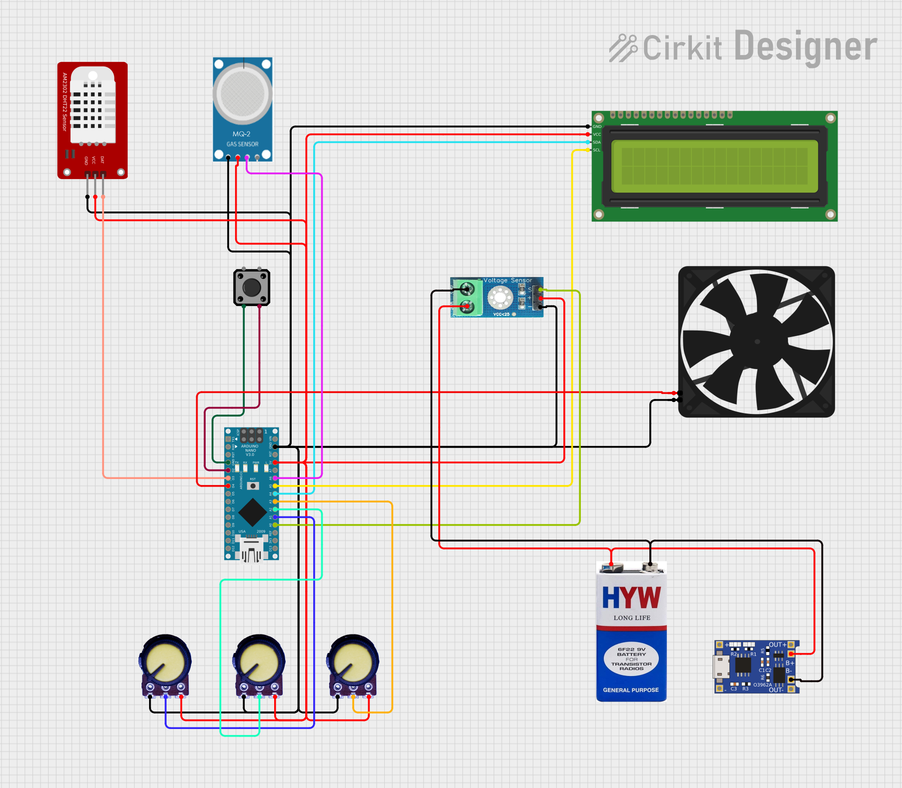
Circuit Documentation
Summary
This circuit is designed to monitor and display various environmental parameters such as temperature, voltage, current, and air quality. It uses an Arduino Nano as the central microcontroller, interfacing with a DHT22 temperature and humidity sensor, a 16x2 I2C LCD for display, a fan for temperature control, a tactile switch button for menu navigation, multiple potentiometers for threshold adjustments, a voltage sensor, and an MQ-2 gas sensor.
Component List
Arduino Nano
- Description: A small, complete, and breadboard-friendly board based on the ATmega328P.
- Pins: D1/TX, D0/RX, RESET, GND, D2, D3, D4, D5, D6, D7, D8, D9, D10, D11/MOSI, D12/MISO, VIN, 5V, A7, A6, A5, A4, A3, A2, A1, A0, AREF, 3V3, D13/SCK
16x2 I2C LCD
- Description: A 16x2 character LCD display with I2C interface.
- Pins: GND, VCC, SDA, SCL
DHT22
- Description: A digital temperature and humidity sensor.
- Pins: GND, VCC, DAT
Potentiometer
- Description: A variable resistor used for adjusting voltage levels.
- Pins: GND, Output, VCC
Tactile Switch Button - 12mm Square
- Description: A push-button switch used for user input.
- Pins: 3, 1, 4, 2
Fan
- Description: A small DC fan used for cooling.
- Pins: GND, 5V
9V Battery
- Description: A standard 9V battery for power supply.
- Pins: +, -
TP4056
- Description: A lithium battery charger module.
- Pins: OUT-, B-, B+, OUT+, IN-, IN+
Voltage Sensor DC 25V
- Description: A sensor module for measuring DC voltage.
- Pins: +, -, output, gnd, vcc
MQ-2
- Description: A gas sensor for detecting various gases.
- Pins: GND, VCC, ANALOG, Digital
Wiring Details
Arduino Nano
- GND: Connected to GND of Tactile Switch Button, DHT22, Fan, Voltage Sensor, 16x2 I2C LCD, MQ-2, and all Potentiometers.
- D2: Connected to pin 4 of Tactile Switch Button.
- D3: Connected to DAT pin of DHT22.
- D4: Connected to 5V pin of Fan.
- 5V: Connected to VCC of DHT22, Voltage Sensor, 16x2 I2C LCD, MQ-2, and all Potentiometers.
- A6: Connected to ANALOG pin of MQ-2.
- A5: Connected to SCL pin of 16x2 I2C LCD.
- A4: Connected to SDA pin of 16x2 I2C LCD.
- A3: Connected to Output pin of one Potentiometer.
- A2: Connected to Output pin of another Potentiometer.
- A1: Connected to Output pin of another Potentiometer.
- A0: Connected to output pin of Voltage Sensor.
16x2 I2C LCD
- GND: Connected to GND of Arduino Nano.
- VCC: Connected to 5V of Arduino Nano.
- SDA: Connected to A4 of Arduino Nano.
- SCL: Connected to A5 of Arduino Nano.
DHT22
- GND: Connected to GND of Arduino Nano.
- VCC: Connected to 5V of Arduino Nano.
- DAT: Connected to D3 of Arduino Nano.
Potentiometers
- GND: Connected to GND of Arduino Nano.
- VCC: Connected to 5V of Arduino Nano.
- Output: Connected to A1, A2, and A3 of Arduino Nano respectively.
Tactile Switch Button
- Pin 3: Connected to GND of Arduino Nano.
- Pin 4: Connected to D2 of Arduino Nano.
Fan
- GND: Connected to GND of Arduino Nano.
- 5V: Connected to D4 of Arduino Nano.
9V Battery
- +: Connected to B+ of TP4056.
- -: Connected to B- of TP4056.
TP4056
- B+: Connected to + of 9V Battery and vcc of Voltage Sensor.
- B-: Connected to - of 9V Battery and gnd of Voltage Sensor.
Voltage Sensor DC 25V
- +: Connected to 5V of Arduino Nano.
- -: Connected to GND of Arduino Nano.
- output: Connected to A0 of Arduino Nano.
- gnd: Connected to B- of TP4056.
- vcc: Connected to B+ of TP4056.
MQ-2
- GND: Connected to GND of Arduino Nano.
- VCC: Connected to 5V of Arduino Nano.
- ANALOG: Connected to A6 of Arduino Nano.
Code Documentation
#include <Wire.h>
#include <LiquidCrystal_I2C.h>
#include <DHT.h>

#define DHTPIN 3           // Pin for DHT22 Sensor
#define DHTTYPE DHT22      // DHT22 Sensor type
#define fanPin 4           // Pin for fan
#define buttonPin 2        // Push button pin
#define voltageSensorPin A0 // Shared pin for voltage and current measurement
#define tempPotPin A1      // Potentiometer for temperature threshold
#define voltPotPin A2      // Potentiometer for voltage demonstration
#define currPotPin A3      // Potentiometer for current demonstration
#define airQualityPin A6   // Pin for MQ135 sensor analog output

DHT dht(DHTPIN, DHTTYPE);
LiquidCrystal_I2C lcd(0x27, 16, 2);

int buttonState = 0;
int menuOption = 0;
float tolerance = 2.0;      // Tolerance for voltage and current comparisons
float loadResistance = 1.8; // Assumed load resistance for current calculations

void setup() {
    pinMode(buttonPin, INPUT_PULLUP);  // Button with pull-up resistor
    pinMode(fanPin, OUTPUT);           // Fan output
    dht.begin();                       // Initialize DHT sensor
    lcd.init();                        // Initialize LCD
    lcd.backlight();                   // Turn on LCD backlight
    Serial.begin(9600);
}

void loop() {
    buttonState = digitalRead(buttonPin);

    if (buttonState == LOW) {          // Button pressed
        menuOption++;
        if (menuOption > 3) menuOption = 0;
        lcd.clear();
        delay(300);                    // Debounce delay
    }

    switch (menuOption) {
        case 0:
            displayTemperature();
            break;
        case 1:
            displayVoltage();
            break;
        case 2:
            displayCurrent();
            break;
        case 3:
            displayAirQuality();
            break;
    }
}

void displayTemperature() {
    int threshold = map(analogRead(tempPotPin), 0, 1023, 20, 40);
    float temperature = dht.readTemperature();

    if (temperature != NAN) {
        digitalWrite(fanPin, threshold > temperature ? HIGH : LOW);
        lcd.setCursor(0, 0);
        lcd.print("Temp: ");
        lcd.print(temperature);
        lcd.print("C");

        lcd.setCursor(0, 1);
        lcd.print("Threshold: ");
        lcd.print(threshold);
        lcd.print("C");
    } else {
        lcd.setCursor(0, 0);
        lcd.print("Error Reading Temp");
    }
    delay(1000);
}

void displayVoltage() {
    int sensorValueV1 = analogRead(voltageSensorPin);
    int sensorValueV2 = analogRead(voltPotPin);

    float measuredVoltageV1 = sensorValueV1 * (5.0 / 1023.0) * 5;
    float measuredVoltageV2 = sensorValueV2 * (5.0 / 1023.0) * 5;

    lcd.setCursor(0, 0);
    lcd.print("V1=");
    lcd.print(measuredVoltageV1, 2);
    lcd.print(" V  ");

    lcd.setCursor(8, 0);
    lcd.print("V2=");
    lcd.print(measuredVoltageV2, 2);
    lcd.print(" V");

    lcd.setCursor(0, 1);
    if (measuredVoltageV