
Raspberry Pi-Based Multi-Input Control System with Rotary Encoders and Proximity Sensor
View and Edit Project In Cirkit Designer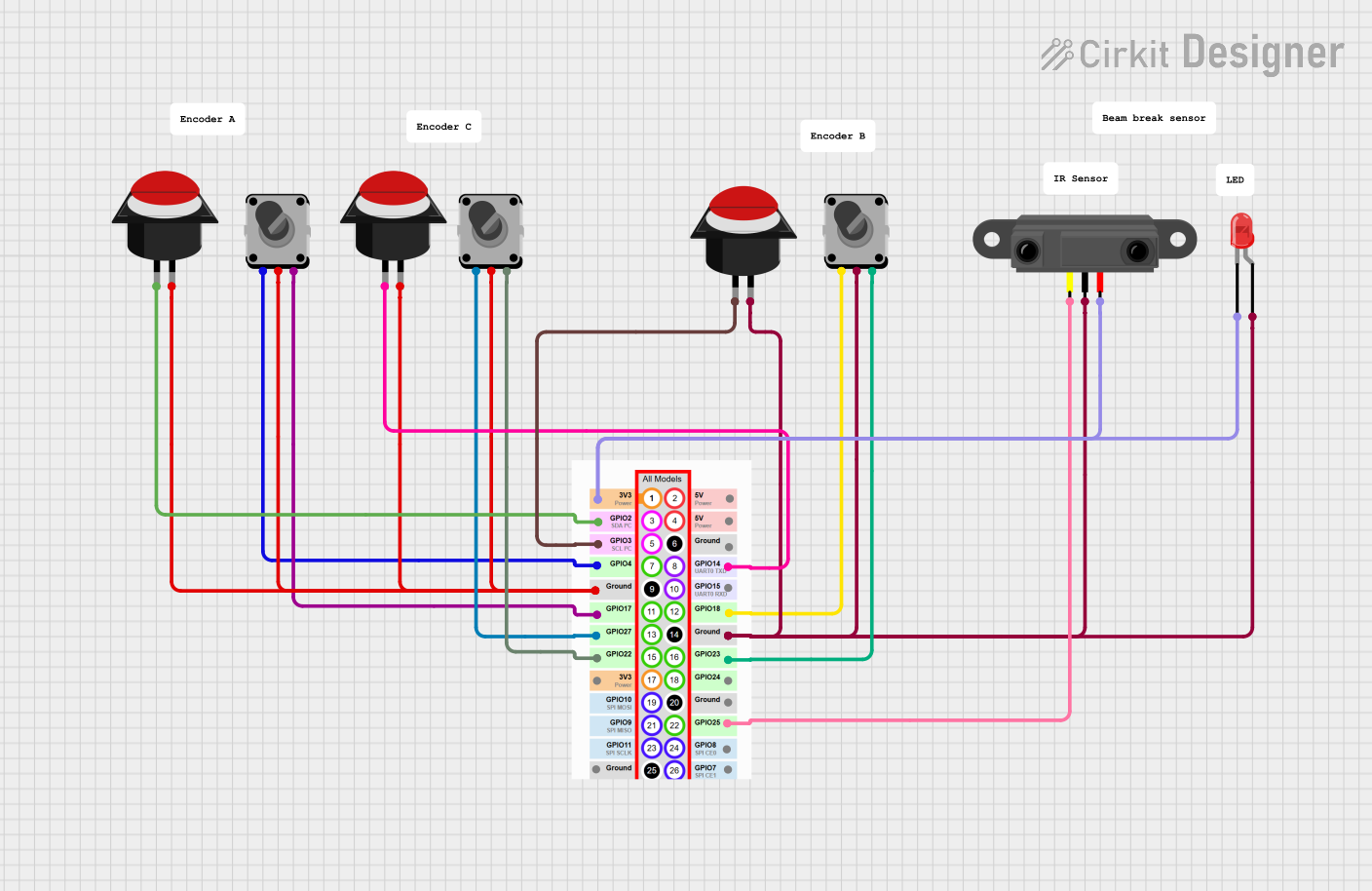
Circuit Documentation
Summary
This document provides a detailed overview of a circuit that includes multiple rotary encoders, push buttons, an infrared proximity sensor, an LED, and a Raspberry Pi. The circuit is designed to interface with the Raspberry Pi's GPIO pins for various input and output operations.
Component List
Rotary Encoder
- Pins: EncoderPinA (output pin A), EncoderPinC (common), EncoderPinB (output pin B)
- Description: A rotary encoder is used to convert the angular position or motion of a shaft or axle to an analog or digital code.
Push Button Round
- Pins: leg0, leg1
- Description: A push button is a simple switch mechanism for controlling some aspect of a machine or a process.
Pi pinout
- Pins: 3.3V, GPIO4, GND, GPIO17, GPIO27, GPIO22, GPIO25, GPIO24, GPIO23, GPIO18, 5V, GPIO2, GPIO3, GPIO14, GPIO8, GPIO15
- Description: The GPIO (General Purpose Input/Output) pins on the Raspberry Pi are used to interface with various components.
Infrared Proximity Sensor
- Pins: Vout, GND, Vcc
- Description: An infrared proximity sensor is used to detect the presence of an object or its distance from the sensor.
LED: Two Pin (red)
- Pins: cathode, anode
- Description: A light-emitting diode (LED) is a semiconductor light source that emits light when current flows through it.
Comment
- Description: Used for adding comments or notes in the circuit design.
Wiring Details
Rotary Encoder 1
- EncoderPinA (output pin A) connected to GPIO4 on the Raspberry Pi.
- EncoderPinC (common) connected to GND on the Raspberry Pi.
- EncoderPinB (output pin B) connected to GPIO17 on the Raspberry Pi.
Rotary Encoder 2
- EncoderPinA (output pin A) connected to GPIO27 on the Raspberry Pi.
- EncoderPinC (common) connected to GND on the Raspberry Pi.
- EncoderPinB (output pin B) connected to GPIO22 on the Raspberry Pi.
Rotary Encoder 3
- EncoderPinA (output pin A) connected to GPIO18 on the Raspberry Pi.
- EncoderPinC (common) connected to GND on the Raspberry Pi.
- EncoderPinB (output pin B) connected to GPIO23 on the Raspberry Pi.
Push Button Round 1
- leg0 connected to GPIO2 on the Raspberry Pi.
- leg1 connected to GND on the Raspberry Pi.
Push Button Round 2
- leg0 connected to GPIO14 on the Raspberry Pi.
- leg1 connected to GND on the Raspberry Pi.
Push Button Round 3
- leg0 connected to GPIO3 on the Raspberry Pi.
- leg1 connected to GND on the Raspberry Pi.
Infrared Proximity Sensor
- Vout connected to GPIO25 on the Raspberry Pi.
- GND connected to GND on the Raspberry Pi.
- Vcc connected to 3.3V on the Raspberry Pi.
LED: Two Pin (red)
- cathode connected to 3.3V on the Raspberry Pi.
- anode connected to GND on the Raspberry Pi.
Documented Code
There is no code provided for the microcontrollers in this circuit.
This document provides a comprehensive overview of the components and their connections in the circuit. Each component is described, and detailed wiring information is provided to ensure proper assembly and functionality.