
Arduino and ESP8266 RFID Access Control System with Servo Gate Operation
View and Edit Project In Cirkit Designer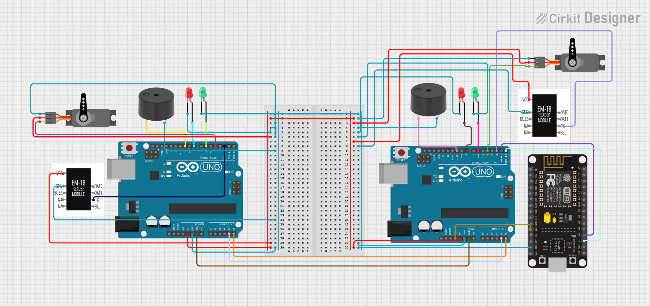
Circuit Documentation
Summary
The circuit in question appears to be a security or access control system utilizing RFID technology for identification and authorization. It includes two Arduino UNO microcontrollers, two EM-18 RFID reader modules, two buzzers, two red LEDs, two green LEDs, two servo motors, and an ESP8266 NodeMCU module. The system is designed to read RFID tags, verify if they are authorized, and then control gates (represented by servo motors) and signal with LEDs and buzzers based on the tag's authorization status.
Component List
Microcontrollers
- Arduino UNO: A microcontroller board based on the ATmega328P, featuring digital and analog I/O pins.
- ESP8266 NodeMCU: A Wi-Fi enabled microcontroller module based on the ESP8266 chip, suitable for IoT applications.
RFID Reader Modules
- EM-18 RFID Reader Module: A module used for reading RFID tags, typically operating at 125 kHz.
Actuators
- Servo: A rotary actuator that allows for precise control of angular position, commonly used for steering mechanisms in remote-controlled vehicles.
Indicators
- Buzzer: An electromechanical component that produces sound, used here as an audible indicator.
- LED: Two Pin (red): A red light-emitting diode used as a visual indicator.
- LED: Two Pin (green): A green light-emitting diode used as a visual indicator.
Wiring Details
Arduino UNO
- Digital Pins:
- D2: Connected to the TX pin of the EM-18 RFID reader module for serial communication.
- D4: Connected to the PWM pin of a Servo motor for gate control.
- D6: Connected to the anode of a green LED.
- D8: Connected to the anode of a red LED.
- D10: Connected to the PIN of a buzzer.
- Analog Pins:
- A4: Interconnected between two Arduino UNOs for I2C communication (SCL).
- A5: Interconnected between two Arduino UNOs for I2C communication (SDA).
- Power Pins:
- 5V: Provides power to the Servo motors and EM-18 RFID reader modules.
- 3.3V: Provides power to the ESP8266 NodeMCU module.
- GND: Common ground for all components.
EM-18 RFID Reader Module
- VCC: Connected to the 5V output of the Arduino UNO.
- GND: Connected to the common ground.
- TX: Connected to the D2 pin of the Arduino UNO for serial communication.
Buzzer
- PIN: Connected to the D10 pin of the Arduino UNO.
- GND: Connected to the common ground.
LED: Two Pin (red)
- Anode: Connected to the D8 pin of the Arduino UNO.
- Cathode: Connected to the common ground.
LED: Two Pin (green)
- Anode: Connected to the D6 pin of the Arduino UNO.
- Cathode: Connected to the common ground.
Servo
- VCC: Connected to the 5V output of the Arduino UNO.
- GND: Connected to the common ground.
- PWM: Connected to the D4 pin of the Arduino UNO for pulse-width modulation control.
ESP8266 NodeMCU
- 3V3: Connected to the 3.3V output of the Arduino UNO.
- GND: Connected to the common ground.
- RX: Connected to the D1 pin of the Arduino UNO for serial communication.
- TX: Connected to the D0 pin of the Arduino UNO for serial communication.
Documented Code
Arduino UNO Code (Instance 1)
#include <SoftwareSerial.h>
#include <Servo.h>  // Include Servo library

#define EM18_TX_PIN 2  // Connect to the TX pin of the EM18 RFID reader
SoftwareSerial rfidReader(EM18_TX_PIN, -1);  // EM18 RFID reader (TX only)

// Servo motor setup
Servo gate_1Servo;
Servo gate_2Servo;

// Struct to hold entry information for each tag
struct TagEntry {
  String tagValue;
  unsigned long entryTime;
  bool entryActive;
};
TagEntry tagEntries[10];  // Array to store entries for up to 10 tags
int currentTagCount = 0;  // Current number of tags stored

const unsigned long MIN_TIME_GAP = 10000;  // Minimum time gap in milliseconds

// List of authorized tags
String authorizedTags[] = {"4D008C7710A6", "4D0089D37166", "4D0089DAF9E7", "4D0089D66072", "4D0089051706"};
int numAuthorizedTags = 5;  // Number of authorized tags

int gate_1Servopin = 4;  // Pin to control the servo motor
int gate_2Servopin = 12;  // Pin to control the servo motor
int led1 = 6;
int led2 = 8;
int buz = 10;

// Setup function
void setup() {
  // ... (initialization code)
}

// Main loop function
void loop() {
  // ... (main loop code)
}

// Additional functions
// ... (helper functions such as readRFID, isAuthorized, etc.)
Arduino UNO Code (Instance 2)
The code for the second instance of the Arduino UNO is identical to the first instance and is therefore not repeated here for brevity.
ESP8266 NodeMCU Code
The code for the ESP8266 NodeMCU is not provided in the input. If it is required, it should be documented similarly to the Arduino UNO code, with appropriate setup and loop functions, and any additional helper functions.
This documentation provides an overview of the circuit, including a description of each component, wiring details, and the embedded code for the microcontrollers. The code is structured to include initialization in the setup() function, the main logic in the loop() function, and additional helper functions for tasks such as reading RFID tags, checking authorization, and controlling gates.