
Arduino Mega 2560 Stepper Motor Controller with LCD Display and Keypad
View and Edit Project In Cirkit Designer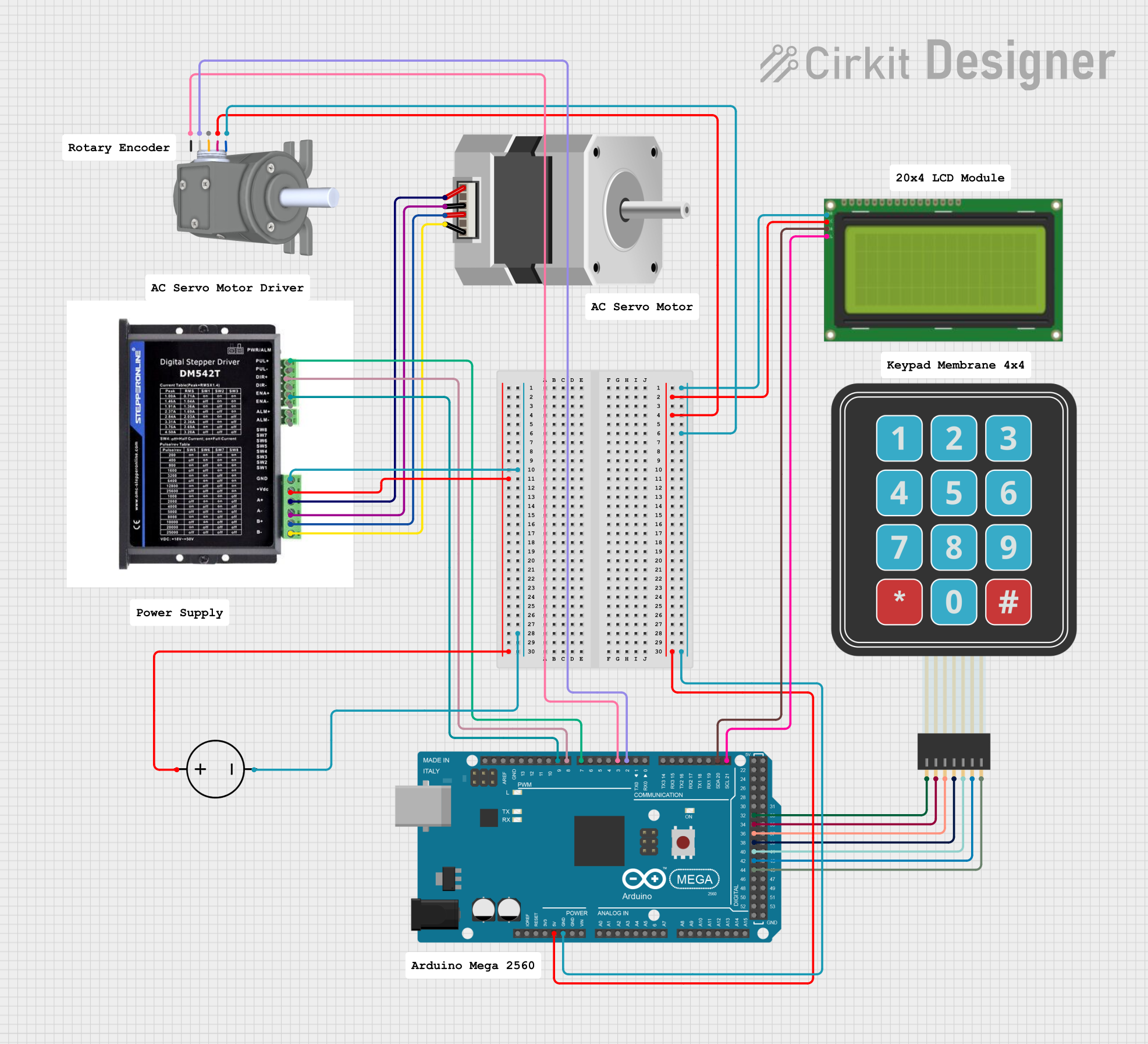
Circuit Documentation
Summary
This circuit is designed to control a stepper motor using a DM542T driver, an Arduino Mega 2560, an LCD display, a membrane keypad, and a rotary encoder. The user can set the rotation angle and speed of the stepper motor using the keypad. The current angle and speed are displayed on the LCD. The rotary encoder is used to fine-tune the angle.
Component List
Stepper Motor (Bipolar)
- Pins: D, B, C, A
- Description: A bipolar stepper motor used for precise control of angular position.
Arduino Mega 2560
- Pins: IOREF, RESET, 3V3, 5V, GND, VIN, A0-A15, D21/SCL, D20/SDA, D19/RX1, D18/TX1, D17 PWM/RX2, D16 PWM/TX2, D15/RX3, D14/TX3, D0 RX0, D1 TX0, D2 PWM, D3 PWM, D4 PWM, D5 PWM, D6 PWM, D7 PWM, D8 PWM, D9 PWM, D10 PWM, D11 PWM, D12 PWM, D13 PWM, AREF, SDA, SCL, D52, D50, D48, D46, D44, D42, D40, D38, D36, D34, D32, D30, D28, D26, D24, D22, D53, D51, D49, D47, D45, D43, D41, D39, D37, D35, D33, D31, D29, D27, D25, D23
- Description: A microcontroller board based on the ATmega2560.
Lcd 20x4 i2c
- Pins: GND, 5V, SCA, SCL
- Description: A 20x4 character LCD display with I2C interface.
Membrane Matrix Keypad
- Pins: Row 1, Row 2, Row 3, Row 4, Column 1, Column 2, Column 3
- Description: A membrane keypad used for user input.
STEPPERONLINE DM542T
- Pins: B-, B+, A-, A+, +V, GND, PUL+, PUL-, DIR+, DIR-, ENA+, ENA-, ALM+, ALM-
- Description: A stepper motor driver.
Rotary Encoder incremental type side mount
- Pins: A, B, Z, VCC, GND
- Description: An incremental rotary encoder used for fine-tuning the angle.
DC Power Source
- Pins: Ground, Positive
- Description: A DC power source for powering the circuit.
Wiring Details
Stepper Motor (Bipolar)
- D connected to B- of STEPPERONLINE DM542T
- B connected to B+ of STEPPERONLINE DM542T
- C connected to A- of STEPPERONLINE DM542T
- A connected to A+ of STEPPERONLINE DM542T
Arduino Mega 2560
- GND connected to GND of Lcd 20x4 i2c and Rotary Encoder incremental type side mount
- 5V connected to 5v of Lcd 20x4 i2c and VCC of Rotary Encoder incremental type side mount
- D7 PWM connected to PUL+ of STEPPERONLINE DM542T
- D8 PWM connected to DIR+ of STEPPERONLINE DM542T
- D9 PWM connected to ENA+ of STEPPERONLINE DM542T
- D3 PWM connected to A of Rotary Encoder incremental type side mount
- D2 PWM connected to B of Rotary Encoder incremental type side mount
- D21/SCL connected to SCL of Lcd 20x4 i2c
- D20/SDA connected to SCA of Lcd 20x4 i2c
- D44 connected to Column 3 of Membrane Matrix Keypad
- D42 connected to Column 2 of Membrane Matrix Keypad
- D40 connected to Column 1 of Membrane Matrix Keypad
- D38 connected to Row 4 of Membrane Matrix Keypad
- D36 connected to Row 3 of Membrane Matrix Keypad
- D34 connected to Row 2 of Membrane Matrix Keypad
- D32 connected to Row 1 of Membrane Matrix Keypad
Lcd 20x4 i2c
- GND connected to GND of Arduino Mega 2560
- 5v connected to 5V of Arduino Mega 2560
- SCA connected to D20/SDA of Arduino Mega 2560
- SCL connected to D21/SCL of Arduino Mega 2560
Membrane Matrix Keypad
- Column 3 connected to D44 of Arduino Mega 2560
- Column 2 connected to D42 of Arduino Mega 2560
- Column 1 connected to D40 of Arduino Mega 2560
- Row 4 connected to D38 of Arduino Mega 2560
- Row 3 connected to D36 of Arduino Mega 2560
- Row 2 connected to D34 of Arduino Mega 2560
- Row 1 connected to D32 of Arduino Mega 2560
STEPPERONLINE DM542T
- GND connected to Ground of DC Power Source
- +V connected to Positive of DC Power Source
- B- connected to D of Stepper Motor (Bipolar)
- B+ connected to B of Stepper Motor (Bipolar)
- A- connected to C of Stepper Motor (Bipolar)
- A+ connected to A of Stepper Motor (Bipolar)
- PUL+ connected to D7 PWM of Arduino Mega 2560
- DIR+ connected to D8 PWM of Arduino Mega 2560
- ENA+ connected to D9 PWM of Arduino Mega 2560
Rotary Encoder incremental type side mount
- GND connected to GND of Arduino Mega 2560
- VCC connected to 5V of Arduino Mega 2560
- A connected to D3 PWM of Arduino Mega 2560
- B connected to D2 PWM of Arduino Mega 2560
DC Power Source
- Ground connected to GND of STEPPERONLINE DM542T
- Positive connected to +V of STEPPERONLINE DM542T
Code Documentation
/*
 * This Arduino sketch controls a stepper motor using a DM542T driver, an LCD
 * display, a membrane keypad, and a rotary encoder. The user can set the
 * rotation angle and speed of the stepper motor using the keypad. The current
 * angle and speed are displayed on the LCD. The rotary encoder is used to
 * fine-tune the angle.
 */

#include <Keypad.h>
#include <Wire.h>
#include <LiquidCrystal_I2C.h>

// Keypad setup
const byte ROWS = 4; // Four rows
const byte COLS = 3; // Three columns
char keys[ROWS][COLS] = {
  {'1','2','3'},
  {'4','5','6'},
  {'7','8','9'},
  {'*','0','#'}
};
byte rowPins[ROWS] = {32, 34, 36, 38}; // Connect to the row pinouts of the keypad
byte colPins[COLS] = {40, 42, 44}; // Connect to the column pinouts of the keypad
Keypad keypad = Keypad(makeKeymap(keys), rowPins, colPins, ROWS, COLS);

// LCD setup
LiquidCrystal_I2C lcd(0x27, 20, 4); // Set the LCD address to 0x27 for a 20x4 display

// Rotary encoder setup
const int encoderPinA = 3;
const int encoderPinB = 2;
volatile int encoderValue = 0;

// Stepper motor driver pins
const int stepPin = 7;
const int dirPin = 8;
const int enablePin