
Arduino Nano-Based Battery-Powered Drone Controller with NRF24L01 and MPU6050
View and Edit Project In Cirkit Designer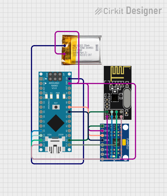
Circuit Documentation
Summary
This circuit is designed to interface an Arduino Nano with an NRF24L01 wireless transceiver and an InvenSense MPU6050 accelerometer and gyroscope sensor. The circuit is powered by a 3.7V LiPo battery. The Arduino Nano reads data from the MPU6050 sensor and transmits it wirelessly using the NRF24L01 module.
Component List
Arduino Nano
- Description: A small, complete, and breadboard-friendly board based on the ATmega328P.
- Pins: D1/TX, D0/RX, RESET, GND, D2, D3, D4, D5, D6, D7, D8, D9, D10, D11/MOSI, D12/MISO, VIN, 5V, A7, A6, A5, A4, A3, A2, A1, A0, AREF, 3V3, D13/SCK
NRF24L01
- Description: A wireless transceiver module for low-power, high-speed communication.
- Pins: IRQ (not used), MOSI, CSN, VCC (3V), GND, CE, SCK, MISO
InvenSense MPU6050
- Description: A 6-axis motion tracking device that combines a 3-axis gyroscope and a 3-axis accelerometer.
- Pins: VCC, GND, SCL, SDA, XDA, XCL, AD0, INT
3.7V LiPo Battery
- Description: A rechargeable lithium polymer battery.
- Pins: +Ve, GND
Wiring Details
Arduino Nano
- D9 connected to CE of NRF24L01
- D10 connected to CSN of NRF24L01
- D11/MOSI connected to MOSI of NRF24L01
- D12/MISO connected to MISO of NRF24L01
- VIN connected to +Ve of 3.7V LiPo Battery
- GND connected to GND of 3.7V LiPo Battery, NRF24L01, and InvenSense MPU6050
- A5 connected to SCL of InvenSense MPU6050
- A4 connected to SDA of InvenSense MPU6050
- 3V3 connected to VCC (3V) of NRF24L01 and VCC of InvenSense MPU6050
- D13/SCK connected to SCK of NRF24L01
NRF24L01
- CE connected to D9 of Arduino Nano
- CSN connected to D10 of Arduino Nano
- MOSI connected to D11/MOSI of Arduino Nano
- MISO connected to D12/MISO of Arduino Nano
- VCC (3V) connected to 3V3 of Arduino Nano
- GND connected to GND of 3.7V LiPo Battery, Arduino Nano, and InvenSense MPU6050
- SCK connected to D13/SCK of Arduino Nano
InvenSense MPU6050
- VCC connected to 3V3 of Arduino Nano
- GND connected to GND of 3.7V LiPo Battery, Arduino Nano, and NRF24L01
- SCL connected to A5 of Arduino Nano
- SDA connected to A4 of Arduino Nano
3.7V LiPo Battery
- +Ve connected to VIN of Arduino Nano
- GND connected to GND of Arduino Nano, NRF24L01, and InvenSense MPU6050
Code Documentation
Arduino Nano Code
#include <SPI.h>
#include <nRF24L01.h>
#include <RF24.h>
#include <Wire.h>
#include <MPU6050.h>

// NRF24L01 Pins
#define CE_PIN 9
#define CSN_PIN 10

RF24 radio(CE_PIN, CSN_PIN);
const byte address[6] = "00001"; // Communication address

// Variables for MPU6050
MPU6050 mpu;
int16_t ax, ay, az, gx, gy, gz;
float pitch, roll, yaw;

// Variables for throttle and control
int throttle = 0; // Throttle value (0 to 255)
int data[4];      // Array to store [throttle, yaw, pitch, roll]

void setup() {
  // Initialize Serial for debugging
  Serial.begin(9600);

  // Initialize MPU6050
  Wire.begin();
  mpu.initialize();
  if (!mpu.testConnection()) {
    Serial.println("MPU6050 connection failed");
    while (1); // Stop if the connection fails
  }

  // Initialize RF24
  radio.begin();
  radio.openWritingPipe(address);
  radio.setPALevel(RF24_PA_LOW);
  radio.stopListening();

  // Debug message
  Serial.println("Controller is ready!");
}

void loop() {
  // Read MPU6050 data
  mpu.getMotion6(&ax, &ay, &az, &gx, &gy, &gz);

  // Calculate pitch and roll
  pitch = atan2(ax, sqrt(ay * ay + az * az)) * 180 / PI;
  roll = atan2(ay, sqrt(ax * ax + az * az)) * 180 / PI;
  yaw = gx / 131.0; // Approximate yaw from gyroscope

  // Debugging sensor data
  Serial.print("Pitch: "); Serial.print(pitch);
  Serial.print(" Roll: "); Serial.print(roll);
  Serial.print(" Yaw: "); Serial.println(yaw);

  // Map pitch, roll, and yaw to control values (0-255)
  data[0] = throttle; // Throttle remains constant for now
  data[1] = map(yaw, -90, 90, 0, 255);
  data[2] = map(pitch, -90, 90, 0, 255);
  data[3] = map(roll, -90, 90, 0, 255);

  // Send data to the drone
  bool success = radio.write(&data, sizeof(data));
  if (success) {
    Serial.println("Data sent!");
  } else {
    Serial.println("Data send failed.");
  }

  delay(50); // Small delay for stability
}
This code initializes the MPU6050 sensor and the NRF24L01 transceiver, reads sensor data, calculates pitch, roll, and yaw, maps these values to control values, and sends the data wirelessly to a receiver.