
ESP32-Controlled Weather Station with BME280 Sensor and Rain Detection
View and Edit Project In Cirkit Designer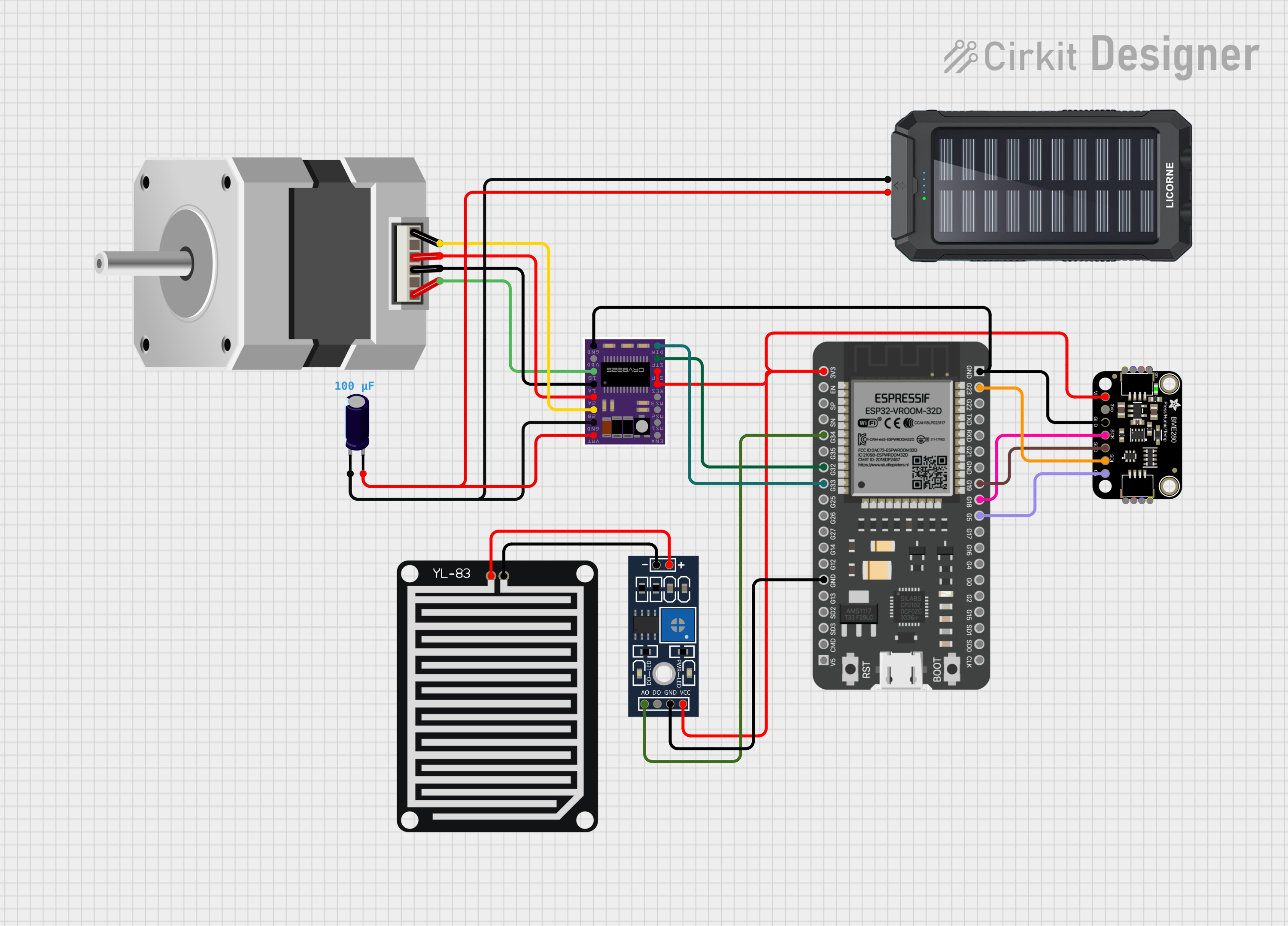
Circuit Documentation
Summary
The circuit in question is designed to interface an ESP32 microcontroller with a variety of sensors and control elements. It includes environmental sensing through an Adafruit BME280 sensor, rain detection via a YL-83 Rain Sensor, and motor control using a DRV8825 stepper motor driver to drive a bipolar stepper motor. A solar charger power bank is included to provide power, and an electrolytic capacitor is used for voltage smoothing or filtering.
Component List
Adafruit BME280
- Description: A precision sensor that can measure humidity, barometric pressure, and temperature.
- Pins: VCC, 3.3V, GND, SCK/SCL, SDO/ADR, SDI/SDA, CS
DRV8825
- Description: A stepper motor driver that controls one bipolar stepper motor.
- Pins: ENABLE, MS1, MS2, MS3, RESET, SLEEP, STEP, DIR, GND, FAULT, 1B, 1A, 2A, 2B, VMOT
YL-83 Rain Sensor - Detection Board
- Description: A board that detects raindrops through the exposed traces on the board.
- Pins: POS, NEG
ESP32 - 38 pins
- Description: A microcontroller with Wi-Fi and Bluetooth capabilities and a wide range of GPIO pins.
- Pins: 3V3, EN, SP, SN, G34, G35, G32, G33, G25, G26, G27, G14, G12, GND, G13, SD2, SD3, CMD, 5V, G23, G22, TXD, RXD, G21, G19, G18, G5, G17, G16, G4, G0, G2, G15, SD1, SD0, CLK
Electrolytic Capacitor
- Description: A capacitor used for filtering and power smoothing.
- Pins: -, +
- Properties: Capacitance: 0.0001 Farads
Solar Charger Power Bank
- Description: A power bank that can be charged via solar power.
- Pins: +, -
Stepper Motor (Bipolar)
- Description: A motor that can be precisely controlled to move in steps.
- Pins: D, B, C, A
YL-83 Rain Sensor - Control Board
- Description: The control board for the YL-83 Rain Sensor.
- Pins: VCC, GND, DO, AO, POS, NEG
Wiring Details
Adafruit BME280
- VCC connected to ESP32 (3V3)
- GND connected to ESP32 (GND)
- SCK/SCL connected to ESP32 (G18)
- SDO/ADR connected to ESP32 (G19)
- SDI/SDA connected to ESP32 (G23)
- CS connected to ESP32 (G5)
DRV8825
- RESET and SLEEP connected to ESP32 (3V3)
- STEP connected to ESP32 (G32)
- DIR connected to ESP32 (G33)
- GND connected to ESP32 (GND) and Electrolytic Capacitor (-)
- VMOT connected to Electrolytic Capacitor (+)
- 1B, 1A, 2A, 2B connected to Stepper Motor (Bipolar) pins D, B, C, A respectively
YL-83 Rain Sensor - Detection Board
- POS connected to YL-83 Rain Sensor - Control Board (POS)
- NEG connected to YL-83 Rain Sensor - Control Board (NEG)
ESP32 - 38 pins
- 3V3 connected to multiple components for power
- GND connected to multiple components for ground
- G34 connected to YL-83 Rain Sensor - Control Board (AO)
- G32 connected to DRV8825 (STEP)
- G33 connected to DRV8825 (DIR)
- G23, G19, G18, G5 connected to Adafruit BME280 for I2C communication and chip select
Electrolytic Capacitor
-
- (negative) connected to DRV8825 (GND) and Solar Charger Power Bank (-)
-
- (positive) connected to DRV8825 (VMOT) and Solar Charger Power Bank (+)
Solar Charger Power Bank
-
- connected to Electrolytic Capacitor (+)
-
- connected to Electrolytic Capacitor (-)
Stepper Motor (Bipolar)
- D, B, C, A connected to DRV8825 pins 2B, 2A, 1A, 1B respectively
YL-83 Rain Sensor - Control Board
- VCC connected to ESP32 (3V3)
- GND connected to ESP32 (GND)
- AO connected to ESP32 (G34)
- POS and NEG connected to YL-83 Rain Sensor - Detection Board (POS, NEG)
Documented Code
No code was provided for the microcontrollers in the circuit. Therefore, this section is left blank until the relevant code is supplied.