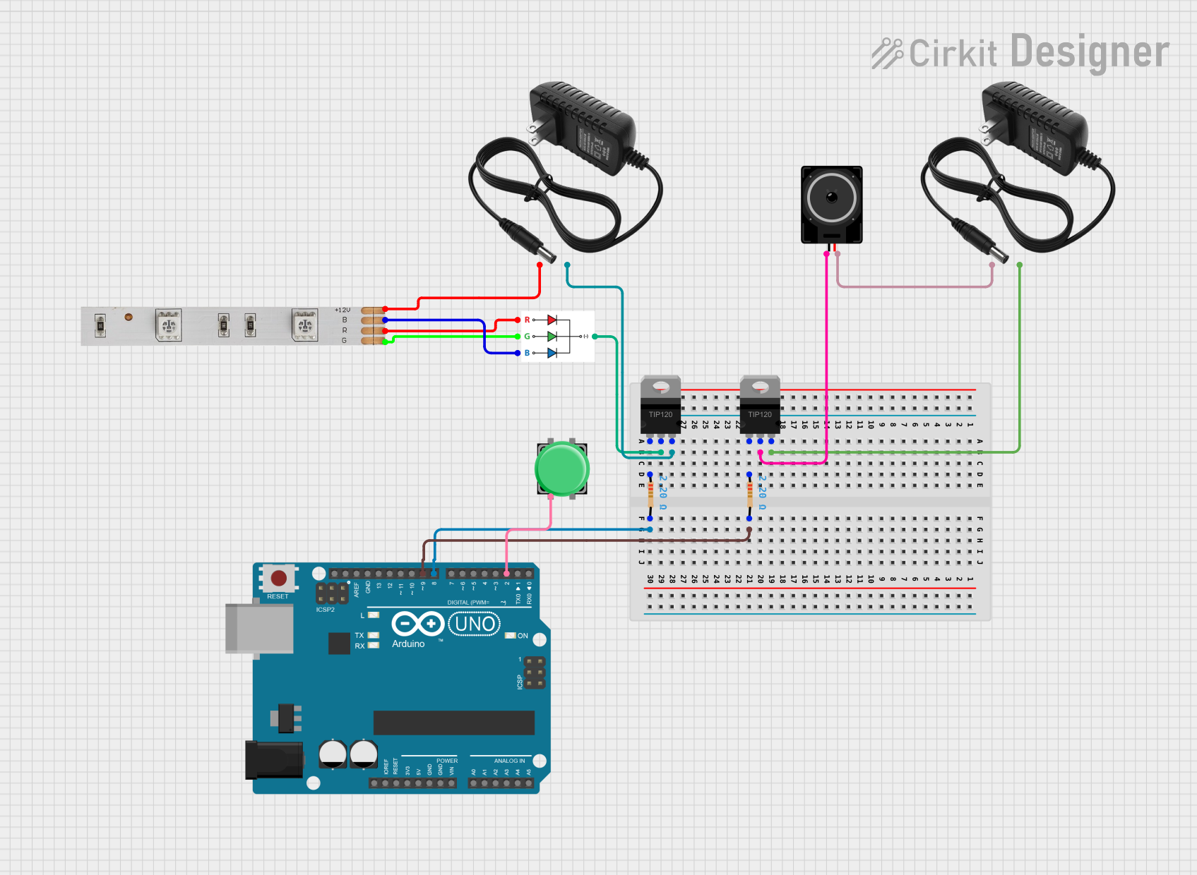
Arduino-Controlled RGB LED and Speaker System with Pushbutton Activation

Circuit Documentation
Summary of the Circuit
This circuit is designed to control an LED strip and a loudspeaker using an Arduino UNO microcontroller. The system is activated by a pushbutton, which when pressed, triggers the Arduino to turn on the LED strip and the loudspeaker for a brief period before turning them off again. The circuit includes two TIP120 high-current Darlington transistors to drive the LED strip and the loudspeaker, which are powered by separate 12V power supplies. Resistors are used to limit the current to the bases of the transistors.
Component List
Arduino UNO
- Microcontroller board based on the ATmega328P
- It has 14 digital input/output pins, 6 analog inputs, a 16 MHz quartz crystal, a USB connection, a power jack, an ICSP header, and a reset button.
LED Strip
- A strip of LEDs that can be controlled to display various colors using the RGB color model.
- Requires a 12V power supply for operation.
RGB LED
- A single LED that can produce a range of colors by mixing red, green, and blue light.
- Commonly used in color display systems.
12V Power Supply (x2)
- Provides the necessary power to the LED strip and the loudspeaker.
- Outputs 12V DC voltage.
TIP120 Hi-Current Darlington Transistor (x2)
- A type of transistor that allows a small current from the microcontroller to control a larger current for high-power devices like the LED strip and loudspeaker.
Resistor (x2)
- An electrical component that limits or regulates the flow of electrical current in an electronic circuit.
- Resistance: 2.2 Ohms
Loudspeaker
- An electroacoustic transducer that converts an electrical audio signal into a corresponding sound.
Pushbutton
- A simple switch mechanism for controlling some aspect of a machine or a process.
Wiring Details
Arduino UNO
D9connected to one end of a resistor (controls the loudspeaker via a transistor).D8connected to one end of another resistor (controls the LED strip via a transistor).D2connected to one side of the pushbutton.
LED Strip
Bconnected to the blue pin of the RGB LED.+12Vconnected to the positive terminal of one 12V power supply.Rconnected to the red pin of the RGB LED.Gconnected to the green pin of the RGB LED.
RGB LED
Bconnected to the blue pin of the LED Strip.Rconnected to the red pin of the LED Strip.Gconnected to the green pin of the LED Strip.GNDconnected to the collector of one TIP120 transistor.
12V Power Supply
+connected to the+12Vpin of the LED Strip and the positive terminal of the loudspeaker.-connected to the emitter of the TIP120 transistors.
TIP120 Hi-Current Darlington Transistor
BASEconnected to the other end of the resistors.COLLECTORconnected to theGNDpin of the RGB LED and one terminal of the loudspeaker.EMITTERconnected to the negative terminal of the 12V power supplies.
Resistor
- One end connected to the
D9andD8pins of the Arduino UNO. - The other end connected to the base of the TIP120 transistors.
Loudspeaker
- One terminal connected to the collector of one TIP120 transistor.
- The other terminal connected to the positive terminal of the second 12V power supply.
Pushbutton
- One side connected to the
D2pin of the Arduino UNO. - The other side is typically connected to ground, but the specific connection is not provided in the net list.
Documented Code
const int buttonPin = 2;      // 按鈕引腳
const int relayLightPin = 8;  // 繼電器控制燈的引腳
const int relaySpeakerPin = 9; // 繼電器控制喇叭的引腳

// 變數
int buttonState = 0;          // 按鈕狀態

void setup() {
    pinMode(buttonPin, INPUT_PULLUP); // 設定按鈕引腳為輸入,啟用內部上拉電阻
    pinMode(relayLightPin, OUTPUT);    // 設定燈的繼電器引腳為輸出
    pinMode(relaySpeakerPin, OUTPUT);  // 設定喇叭的繼電器引腳為輸出

    // 初始關閉燈和喇叭
    digitalWrite(relayLightPin, HIGH);
    digitalWrite(relaySpeakerPin, HIGH);
}

void loop() {
    // 讀取按鈕狀態
    buttonState = digitalRead(buttonPin);

    // 如果按鈕被按下(LOW 狀態),則重啟燈和喇叭
    if (buttonState == LOW) {
        // 開啟燈和喇叭
        digitalWrite(relayLightPin, LOW);
        digitalWrite(relaySpeakerPin, LOW);

        // 等待 1 秒
        delay(1000);

        // 關閉燈和喇叭
        digitalWrite(relayLightPin, HIGH);
        digitalWrite(relaySpeakerPin, HIGH);

        // 等待一段時間以避免重複觸發
        delay(2000);
    }
}
The code is written for the Arduino UNO microcontroller. It initializes the button and relay control pins, sets an initial state for the relays, and contains a loop that checks the button state. If the button is pressed, it activates the relays to turn on the LED strip and loudspeaker for one second, then turns them off and waits for two seconds to prevent immediate re-triggering.