
Arduino UNO Controlled Robot with Bluetooth, IR Sensors, and Servo Motor
View and Edit Project In Cirkit Designer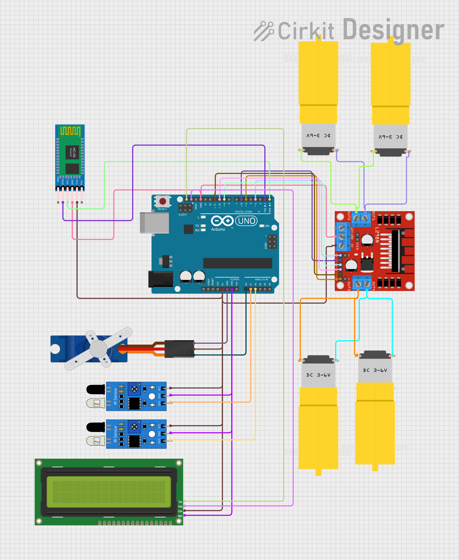
Circuit Documentation
Summary
This circuit is designed around an Arduino UNO microcontroller, which serves as the central processing unit. The circuit includes various peripherals such as motors, sensors, a motor driver, a servo, a Bluetooth module, and an I2C LCD screen. The Arduino UNO controls these components, allowing for a range of functionalities from motor control to wireless communication and display interfacing.
Component List
- Arduino UNO: A microcontroller board based on the ATmega328P. It has a variety of digital and analog I/O pins and is used for controlling the other components in the circuit.
- Motor Amarillo Motorreductor Hobby: These are hobbyist DC motors used for driving mechanisms that require rotational movement.
- L298N DC Motor Driver: An integrated circuit that allows for controlling the direction and speed of DC motors.
- Tower Pro SG90 Servo: A small and lightweight servo motor capable of precise position control.
- IR Sensor: An infrared sensor used for detecting objects or motion within its field of view.
- HC-05 Bluetooth Module: A wireless communication module that enables Bluetooth connectivity for the Arduino.
- I2C LCD 16x2 Screen: A liquid crystal display that can show 16 characters per line and has 2 lines. It uses the I2C communication protocol for interfacing with the Arduino.
Wiring Details
Arduino UNO
- 5V: Powers the I2C LCD screen, IR sensors, HC-05 Bluetooth Module, L298N motor driver, and Tower Pro SG90 servo.
- GND: Common ground for the Tower Pro SG90 servo, I2C LCD screen, IR sensors, HC-05 Bluetooth Module, and L298N motor driver.
- A0: Connected to the signal pin of the Tower Pro SG90 servo.
- A1: Connected to the output pin of one IR sensor.
- A2: Connected to the output pin of another IR sensor.
- SCL: Connected to the SCL pin of the I2C LCD screen.
- SDA: Connected to the SDA pin of the I2C LCD screen.
- D11: Connected to the IN4 pin of the L298N motor driver.
- D10: Connected to the IN3 pin of the L298N motor driver.
- D9: Connected to the IN2 pin of the L298N motor driver.
- D6: Connected to the IN1 pin of the L298N motor driver.
- D5: Connected to the ENB pin of the L298N motor driver.
- D3: Connected to the ENA pin of the L298N motor driver.
- D1: Connected to the RXD pin of the HC-05 Bluetooth Module.
- D0: Connected to the TXD pin of the HC-05 Bluetooth Module.
Motor Amarillo Motorreductor Hobby
- vcc: Connected to the OUT1 and OUT2 pins of the L298N motor driver for two motors, and OUT3 and OUT4 for the other two motors.
- GND: Shares the same connections as the VCC pins but on the corresponding OUT pins for ground.
L298N DC Motor Driver
- 5V: Receives power from the Arduino UNO.
- GND: Connected to the common ground in the circuit.
- OUT1, OUT2, OUT3, OUT4: Connected to the VCC and GND pins of the Motor Amarillo motorreductors.
Tower Pro SG90 Servo
- Signal: Connected to the A0 pin of the Arduino UNO.
- +5V: Powered by the 5V pin of the Arduino UNO.
- GND: Connected to the common ground.
IR Sensor
- out: One sensor's output is connected to A1 on the Arduino UNO, and the other to A2.
- gnd: Connected to the common ground.
- vcc: Powered by the 5V pin of the Arduino UNO.
HC-05 Bluetooth Module
- VCC: Powered by the 5V pin of the Arduino UNO.
- GND: Connected to the common ground.
- TXD: Connected to the D0 pin of the Arduino UNO.
- RXD: Connected to the D1 pin of the Arduino UNO.
I2C LCD 16x2 Screen
- SCL: Connected to the SCL pin of the Arduino UNO.
- SDA: Connected to the SDA pin of the Arduino UNO.
- VCC (5V): Powered by the 5V pin of the Arduino UNO.
- GND: Connected to the common ground.
Documented Code
Arduino UNO Code (sketch.ino)
void setup() {
  // put your setup code here, to run once:

}

void loop() {
  // put your main code here, to run repeatedly:

}
This is a template for the Arduino sketch. The setup() function is called once when the program starts and is used to initialize the settings. The loop() function is called repeatedly and contains the main logic of the program. The actual implementation details will depend on the specific requirements of the circuit's operation.