
Circuit Documentation
Summary
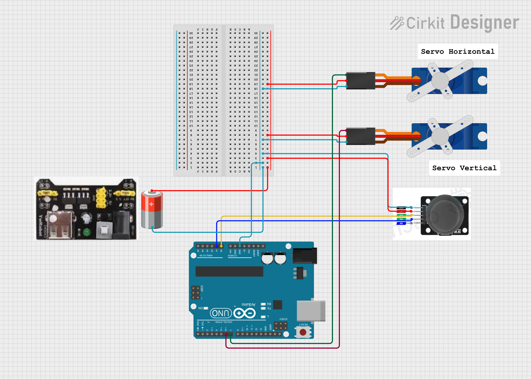
The circuit consists of an Arduino UNO microcontroller interfaced with two Tower Pro SG90 servos and a joystick module. The servos are controlled by the Arduino, which reads the joystick's position to determine the servo angles. A 5V battery provides power to the system, ensuring that the servos and the joystick module have a stable voltage supply.
Component List
Arduino UNO
- Microcontroller board based on the ATmega328P
- It has 14 digital input/output pins, 6 analog inputs, a 16 MHz quartz crystal, a USB connection, a power jack, an ICSP header, and a reset button.
Tower Pro SG90 Servo (x2)
- A small and lightweight servo motor capable of precise control
- It operates on 4.8V to 6V and offers good torque for its size.
Joystick Module
- An input device that can measure two-dimensional movement (X and Y axis)
- It typically includes a push button (not used in this circuit) and two potentiometers to measure the stick's position.
5V Battery
- Power source for the circuit
- Provides a stable 5V supply to the components.
Wiring Details
Arduino UNO
GNDconnected to the negative terminal of the 5V battery and ground pins of other components.A0connected to theVRXpin of the Joystick module to read the X-axis position.A1connected to theVRYpin of the Joystick module to read the Y-axis position.D6connected to theSignalpin of one Tower Pro SG90 servo.D7connected to theSignalpin of the other Tower Pro SG90 servo.
Tower Pro SG90 Servo
Signalpin connected to the corresponding digital pin on the Arduino UNO for control signals.+5Vpin connected to the positive terminal of the 5V battery.GNDpin connected to the ground network.
Joystick Module
VRXconnected toA0on the Arduino UNO to read the X-axis position.VRYconnected toA1on the Arduino UNO to read the Y-axis position.VCCconnected to the positive terminal of the 5V battery.GNDconnected to the ground network.
5V Battery
+terminal connected to theVCCor+5Vpins of the Joystick module and both Tower Pro SG90 servos.-terminal connected to theGNDpins of the Arduino UNO, Joystick module, and both Tower Pro SG90 servos.
Documented Code
// Code for controlling servos with a joystick using an Arduino UNO
const int xPin = A0, yPin = A1;
float xValue, yValue;

void setup() {
  pinMode(xPin, INPUT);
  pinMode(yPin, INPUT);
  Serial.begin(9600);
}

void loop() {
  xValue = analogRead(xPin);
  yValue = analogRead(yPin);

  Serial.print("Value of x-axis: ");
  Serial.println(xValue);
  Serial.print("Value of y-axis: ");
  Serial.println(yValue);

  delay(100);
}
This code initializes the Arduino to read the X and Y positions of the joystick and outputs the values to the serial monitor. The analog pins A0 and A1 are configured as inputs to read the voltage variations as the joystick is moved. The Serial.begin(9600); line sets up the serial communication at a baud rate of 9600. The loop() function continuously reads the joystick's position and prints the values to the serial monitor. The delay(100); line introduces a 100ms delay between each reading to make the output readable.