
Solar-Powered LED Lighting System with Capacitive Energy Storage and Pushbutton Control
View and Edit Project In Cirkit Designer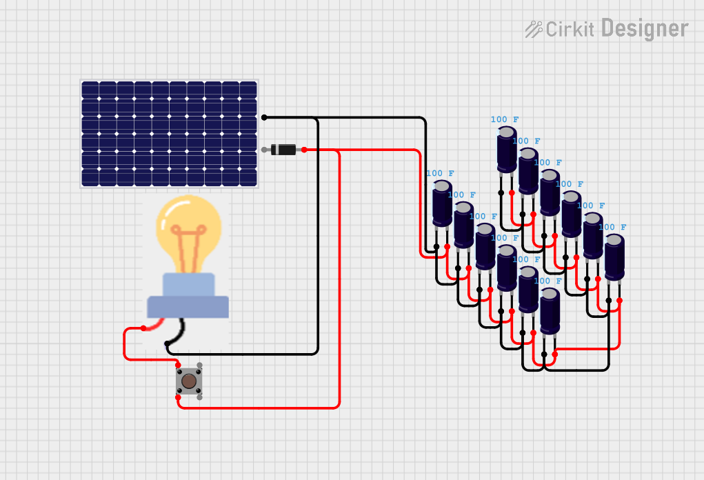
Circuit Documentation
Summary of the Circuit
The circuit appears to be a simple power supply circuit with a solar panel as the power source. The solar panel's output is connected to a series of electrolytic capacitors, likely for smoothing out the voltage. A diode is included, possibly for preventing reverse current flow back into the solar panel. A bulb is included as a load, and it is controlled by a pushbutton. The pushbutton likely serves as an on/off switch for the bulb. There is no microcontroller or embedded code involved in this circuit.
Component List
Solar Panel
- Description: A device that converts light into electrical energy.
- Purpose: Acts as the power source for the circuit.
Diode
- Description: A semiconductor device with two terminals, typically allowing the flow of current in one direction only.
- Purpose: Prevents reverse current flow, protecting the circuit from potential damage.
Electrolytic Capacitors (12x)
- Description: A type of capacitor with a larger capacitance per unit volume than other types, used for energy storage and filtering.
- Purpose: Smooths out the voltage from the solar panel, reducing voltage spikes and dips.
Bulb
- Description: An electric light with a wire filament heated until it glows.
- Purpose: Acts as an indicator or a load for the circuit.
Pushbutton
- Description: A simple switch mechanism for controlling some aspect of a machine or a process.
- Purpose: Controls the power to the bulb, acting as an on/off switch.
Wiring Details
Solar Panel
- Positive Pin: Connected to the positive pins of all electrolytic capacitors through the anode of the diode.
- Negative Pin: Connected to the negative pins of all electrolytic capacitors and the GND pin of the bulb.
Diode
- Anode: Connected to the positive pin of the solar panel.
- Cathode: Connected to the positive pins of all electrolytic capacitors.
Electrolytic Capacitors
- Positive Pin: All connected together and to the anode of the diode.
- Negative Pin: All connected together and to the GND pin of the bulb and the negative pin of the solar panel.
Bulb
- GND Pin: Connected to the negative pins of all electrolytic capacitors.
- Power Pin: Connected to one of the pushbutton pins.
Pushbutton
- Pin 1 (in): Connected to the power pin of the bulb.
- Pin 2 (in): Connected to the positive pins of all electrolytic capacitors.
- Pin 3 (out) and Pin 4 (out): Not connected in the current configuration.
Documented Code
There is no embedded code provided for this circuit as there are no microcontroller components involved.