
Raspberry Pi 4B Controlled Stepper Motor with Magnetic Encoder
View and Edit Project In Cirkit Designer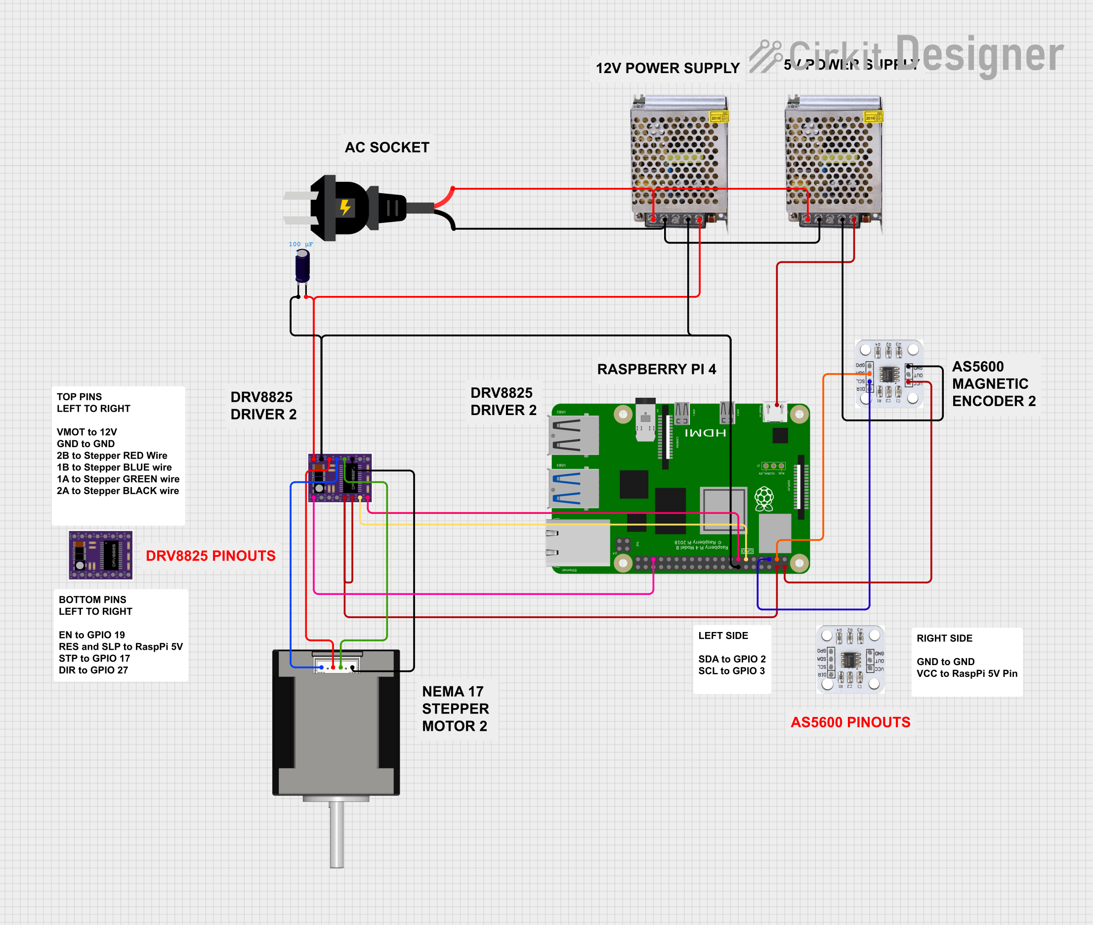
Circuit Documentation
Summary
This document provides a detailed overview of a circuit that includes a Raspberry Pi 4B, DRV8825 motor drivers, AS5600 magnetic encoders, power supplies, an AC source, an electrolytic capacitor, and a Nema 17 stepper motor. The circuit is designed to control a stepper motor using the Raspberry Pi, with feedback from the magnetic encoders. The power supplies provide the necessary voltages for the components.
Component List
DRV8825 Motor Driver
- Description: Motor driver for controlling stepper motors.
- Pins: ENABLE, MS1, MS2, MS3, RESET, SLEEP, STEP, DIR, GND, FAULT, 1B, 1A, 2A, 2B, VMOT
AS5600 Magnetic Encoder
- Description: Magnetic encoder for position feedback.
- Pins: DIR, SCL, SDA, GP0, VCC, OUT, GND
POWER SUPPLY 12V 5AMP
- Description: Power supply providing 12V DC at 5A.
- Pins: 220V Positive Pole (AC), 220V Negative Pole (AC), GND, GND (DC), 12V-24V Output (DC)
POWER SUPPLY 5V 5AMP
- Description: Power supply providing 5V DC at 5A.
- Pins: 220V Positive Pole (AC), 220V Negative Pole (AC), GND, GND (DC), 12V-24V Output (DC)
Raspberry Pi 4B
- Description: Single-board computer for controlling the circuit.
- Pins: 3V3, 5V, GPIO2, GPIO3, GND, GPIO4, GPIO14, GPIO15, GPIO17, GPIO18, GPIO27, GPIO22, GPIO23, GPIO24, GPIO10, GPIO9, GPIO25, GPIO11, GPIO8, GPIO7, ID_SD, GPIO5, GPIO6, GPIO12, GPIO13, GPIO19, GPIO16, GPIO26, GPIO20, GPIO21, ID_SC, TR01_TAP, TR00_TAP, TR03_TAP, TR02_TAP, RUN, GLOBAL_EN
AC Source
- Description: AC power source.
- Pins: +, -
Nema 17 42-STH48
- Description: Stepper motor.
- Pins: A2 (black), A1 Green, B2 Red, B1 Blue
Electrolytic Capacitor
- Description: Capacitor for filtering.
- Pins: -, +
- Properties: Capacitance: 0.0001 Farads
Wiring Details
DRV8825 Motor Driver
- RESET connected to SLEEP and 5V of Raspberry Pi 4B
- STEP connected to GPIO17 of Raspberry Pi 4B
- DIR connected to GPIO27 of Raspberry Pi 4B
- GND connected to - of Electrolytic Capacitor, GND (DC) of POWER SUPPLY 12V 5AMP, and GND of Raspberry Pi 4B
- ENABLE connected to GPIO19 of Raspberry Pi 4B
- VMOT connected to + of Electrolytic Capacitor and 12V-24V Output (DC) of POWER SUPPLY 12V 5AMP
- 1B connected to A2 (black) of Nema 17 42-STH48
- 1A connected to A1 Green of Nema 17 42-STH48
- 2A connected to B1 Blue of Nema 17 42-STH48
- 2B connected to B2 Red of Nema 17 42-STH48
AS5600 Magnetic Encoder
- VCC connected to 5V of Raspberry Pi 4B
- SDA connected to GPIO2 of Raspberry Pi 4B
- SCL connected to GPIO3 of Raspberry Pi 4B
- GND connected to GND (DC) of POWER SUPPLY 5V 5AMP
POWER SUPPLY 12V 5AMP
- 220V Positive Pole (AC) connected to + of AC source
- 220V Negative Pole (AC) connected to - of AC source
- GND (DC) connected to GND of DRV8825, - of Electrolytic Capacitor, and GND of Raspberry Pi 4B
- 12V-24V Output (DC) connected to VMOT of DRV8825 and + of Electrolytic Capacitor
POWER SUPPLY 5V 5AMP
- 220V Positive Pole (AC) connected to + of AC source
- 220V Negative Pole (AC) connected to - of AC source
- GND (DC) connected to GND of AS5600 magnetic encoder
- 12V-24V Output (DC) connected to Raspberry Pi 4B
Raspberry Pi 4B
- 5V connected to RESET and SLEEP of DRV8825, and VCC of AS5600 magnetic encoder
- GPIO2 connected to SDA of AS5600 magnetic encoder
- GPIO3 connected to SCL of AS5600 magnetic encoder
- GPIO17 connected to STEP of DRV8825
- GPIO27 connected to DIR of DRV8825
- GPIO19 connected to ENABLE of DRV8825
- GND connected to GND of DRV8825, - of Electrolytic Capacitor, and GND (DC) of POWER SUPPLY 12V 5AMP
AC Source
- + connected to 220V Positive Pole (AC) of POWER SUPPLY 12V 5AMP and POWER SUPPLY 5V 5AMP
- - connected to 220V Negative Pole (AC) of POWER SUPPLY 12V 5AMP and POWER SUPPLY 5V 5AMP
Nema 17 42-STH48
- A2 (black) connected to 1B of DRV8825
- A1 Green connected to 1A of DRV8825
- B1 Blue connected to 2A of DRV8825
- B2 Red connected to 2B of DRV8825
Electrolytic Capacitor
- - connected to GND of DRV8825, GND (DC) of POWER SUPPLY 12V 5AMP, and GND of Raspberry Pi 4B
- + connected to VMOT of DRV8825 and 12V-24V Output (DC) of POWER SUPPLY 12V 5AMP
Code
No code is provided for this circuit.
This document provides a comprehensive overview of the circuit, including a summary, component list, wiring details, and code section. Each component is described, and the wiring details are provided to ensure proper connections.