Cirkit Designer
Your all-in-one circuit design IDE
Home /
Project Documentation
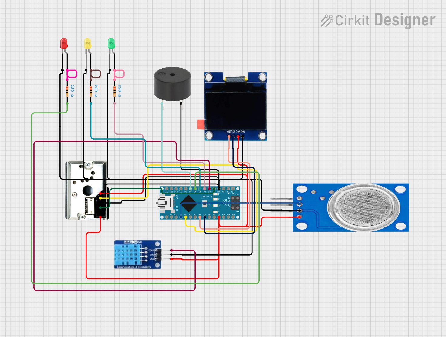
Arduino Nano Environmental Monitoring System with OLED Display and Alarm Indicators
Circuit Documentation
Summary
This circuit is designed to monitor environmental conditions such as gas levels, dust density, temperature, and humidity. It uses an Arduino Nano microcontroller to read data from various sensors and display the information on an OLED screen. The circuit also includes LEDs and a buzzer to provide visual and auditory alerts based on predefined threshold values.
Component List
Arduino Nano
- Description: Microcontroller board based on the ATmega328P.
- Pins: D1/TX, D0/RX, RESET, GND, D2, D3, D4, D5, D6, D7, D8, D9, D10, D11/MOSI, D12/MISO, VIN, 5V, A7, A6, A5, A4, A3, A2, A1, A0, AREF, 3V3, D13/SCK
DHT11
- Description: Digital temperature and humidity sensor.
- Pins: DATA, GND, VCC
Buzzer
- Description: Simple piezoelectric buzzer for sound alerts.
- Pins: PIN, GND
LED: Two Pin (red)
- Description: Red LED for visual alerts.
- Pins: cathode, anode
LED: Two Pin (green)
- Description: Green LED for visual alerts.
- Pins: cathode, anode
LED: Two Pin (yellow)
- Description: Yellow LED for visual alerts.
- Pins: cathode, anode
Resistor (220 Ohms)
- Description: Resistor to limit current through LEDs.
- Pins: pin1, pin2
- Properties: Resistance: 220 Ohms
GP2Y1010AU0F
- Description: Optical dust sensor.
- Pins: VCC, Vout, S-GND, LED, LED-GND, V-LED
MQ135
- Description: Gas sensor for air quality monitoring.
- Pins: VCC, GND, A0, D0
OLED 1.3"
- Description: OLED display for visual output.
- Pins: GND, VCC, SCL, SDA
Wiring Details
Arduino Nano
- GND: Connected to GND of DHT11, Buzzer, Red LED, Green LED, Yellow LED, GP2Y1010AU0F (S-GND and LED-GND), MQ135, and OLED 1.3".
- 5V: Connected to VCC of DHT11, Buzzer, GP2Y1010AU0F (VCC and V-LED), MQ135, and OLED 1.3".
- D2: Connected to LED pin of GP2Y1010AU0F.
- D3: Connected to DATA pin of DHT11.
- D4: Connected to pin2 of a 220 Ohm resistor (Green LED).
- D5: Connected to pin2 of a 220 Ohm resistor (Yellow LED).
- D6: Connected to pin2 of a 220 Ohm resistor (Red LED).
- D7: Connected to PIN of Buzzer.
- A5: Connected to SCL pin of OLED 1.3".
- A4: Connected to SDA pin of OLED 1.3".
- A1: Connected to Vout pin of GP2Y1010AU0F.
- A0: Connected to A0 pin of MQ135.
DHT11
- GND: Connected to GND of Arduino Nano.
- VCC: Connected to 5V of Arduino Nano.
- DATA: Connected to D3 of Arduino Nano.
Buzzer
- GND: Connected to GND of Arduino Nano.
- PIN: Connected to D7 of Arduino Nano.
LED: Two Pin (red)
- cathode: Connected to GND of Arduino Nano.
- anode: Connected to pin1 of a 220 Ohm resistor.
- Resistor pin2: Connected to D6 of Arduino Nano.
LED: Two Pin (green)
- cathode: Connected to GND of Arduino Nano.
- anode: Connected to pin1 of a 220 Ohm resistor.
- Resistor pin2: Connected to D4 of Arduino Nano.
LED: Two Pin (yellow)
- cathode: Connected to GND of Arduino Nano.
- anode: Connected to pin1 of a 220 Ohm resistor.
- Resistor pin2: Connected to D5 of Arduino Nano.
GP2Y1010AU0F
- S-GND: Connected to GND of Arduino Nano.
- LED-GND: Connected to GND of Arduino Nano.
- VCC: Connected to 5V of Arduino Nano.
- V-LED: Connected to 5V of Arduino Nano.
- LED: Connected to D2 of Arduino Nano.
- Vout: Connected to A1 of Arduino Nano.
MQ135
- GND: Connected to GND of Arduino Nano.
- VCC: Connected to 5V of Arduino Nano.
- A0: Connected to A0 of Arduino Nano.
OLED 1.3"
- GND: Connected to GND of Arduino Nano.
- VCC: Connected to 5V of Arduino Nano.
- SCL: Connected to A5 of Arduino Nano.
- SDA: Connected to A4 of Arduino Nano.
Code Documentation
// Include necessary libraries
#include <Adafruit_SSD1306.h>
#include <Adafruit_GFX.h>
#include <Wire.h>
#include <DHT.h>

// Pin definitions
#define MQ135_PIN A0
#define DHT_PIN 2
#define BUZZER_PIN 7
#define GREEN_LED_PIN 4
#define YELLOW_LED_PIN 5
#define RED_LED_PIN 6
#define DUST_LED_PIN 3
#define DUST_SENSOR_PIN A1

// DHT sensor setup
#define DHT_TYPE DHT11
DHT dht(DHT_PIN, DHT_TYPE);

// OLED display setup
#define SCREEN_WIDTH 128
#define SCREEN_HEIGHT 64
Adafruit_SSD1306 display(SCREEN_WIDTH, SCREEN_HEIGHT, &Wire, -1); // OLED display

// Threshold values for alarms
const int MQ135_THRESHOLD = 300;  // Example value for gas level
const int DUST_THRESHOLD = 150;   // Example value for dust density
const float TEMP_THRESHOLD = 30.0; // Example value for temperature in °C

void setup() {
  // Initialize Serial Monitor
  Serial.begin(9600);

  // Initialize pins
  pinMode(GREEN_LED_PIN, OUTPUT);
  pinMode(YELLOW_LED_PIN, OUTPUT);
  pinMode(RED_LED_PIN, OUTPUT);
  pinMode(BUZZER_PIN, OUTPUT);
  pinMode(DUST_LED_PIN, OUTPUT);

  // Initialize DHT sensor
  dht.begin();

  // Initialize OLED display
  if (!display.begin(SSD1306_SWITCHCAPVCC, 0x3C)) {
    Serial.println(F("SSD1306 allocation failed"));
    for (;;);
  }
  display.clearDisplay();

  // Start with LEDs and buzzer off
  digitalWrite(GREEN_LED_PIN, LOW);
  digitalWrite(YELLOW_LED_PIN, LOW);
  digitalWrite(RED_LED_PIN, LOW);
  digitalWrite(BUZZER_PIN, LOW);
}

void loop() {
  // Read gas level from MQ-135
  int mq135_value = analogRead(MQ135_PIN);
  Serial.print("Gas level: ");
  Serial.println(mq135_value);

  // Read dust density from GP2Y1010AU0F
  digitalWrite(DUST_LED_PIN, LOW); // Turn on IR LED for dust sensor
  delayMicroseconds(280);
  int dust_value = analogRead(DUST_SENSOR_PIN);
  delayMicroseconds(40);
  digitalWrite(DUST_LED_PIN, HIGH); // Turn off IR LED
  Serial.print("Dust density: ");
  Serial.println(dust_value);

  // Read temperature and humidity from DHT11
  float temperature = dht.readTemperature();
  float humidity = dht.readHumidity();
  Serial.print("Temperature: ");
  Serial.println(temperature);
  Serial.print("Humidity: ");
  Serial.println(humidity);

  // Display data on OLED
  display.clearDisplay();
  display.setTextSize(1);
  display.setTextColor(SSD1306_WHITE);
  display.setCursor(0, 0);
  display.print("Gas Level: ");
  display.println(mq135_value);
  display.print("Dust: ");
  display.println(dust_value);
  display.print("Temp: ");
  display.print(temperature);
  display.println(" C");
  display.print("Humidity: ");
  display.print(humidity);
  display.println(" %");
  display.display();

  // LED and buzzer alerts based on thresholds
  if (