
Arduino Nano-Based Gas Detection System with OLED Display and Alarm
View and Edit Project In Cirkit Designer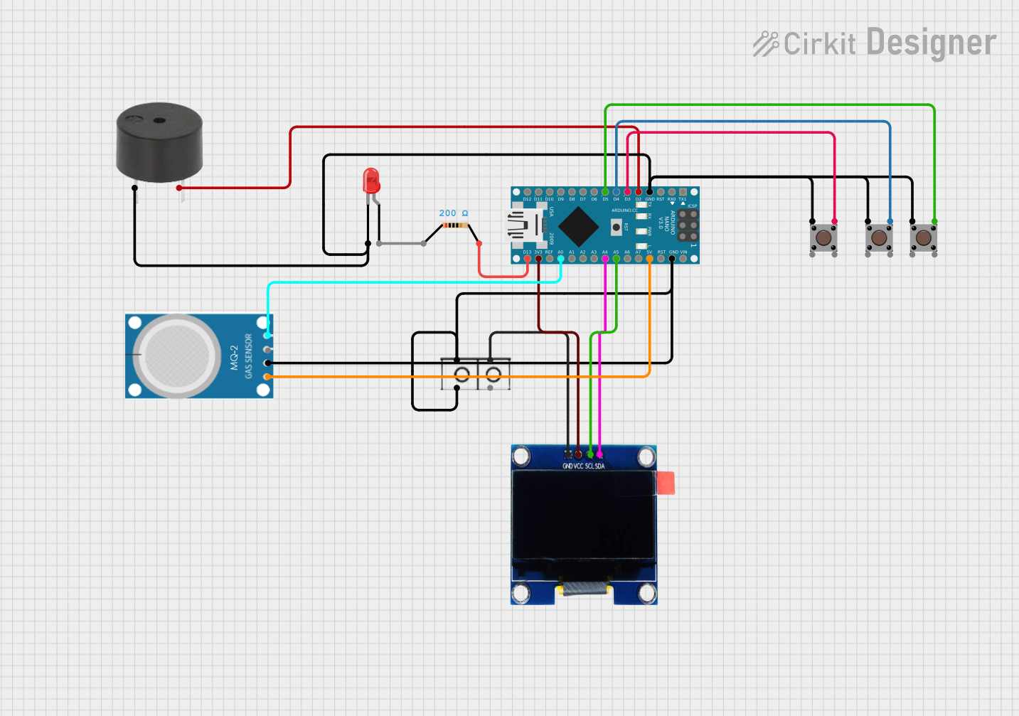
Circuit Documentation
Summary
This circuit is designed to monitor air quality using an MQ-2 gas sensor and display the results on an OLED screen. It also includes a buzzer and an LED to provide audible and visual alerts when certain gas levels are detected. The circuit is controlled by an Arduino Nano, which reads the sensor data, processes it, and updates the display and alerts accordingly. Three pushbuttons are used to control the mode and alarm state.
Component List
Arduino Nano
- Description: Microcontroller board based on the ATmega328P.
- Pins: D1/TX, D0/RX, RESET, GND, D2, D3, D4, D5, D6, D7, D8, D9, D10, D11/MOSI, D12/MISO, VIN, 5V, A7, A6, A5, A4, A3, A2, A1, A0, AREF, 3V3, D13/SCK
Buzzer
- Description: A simple piezoelectric buzzer.
- Pins: PIN, GND
LED: Two Pin (red)
- Description: A standard red LED.
- Pins: cathode, anode
Pushbutton
- Description: A simple pushbutton switch.
- Pins: Pin 3 (out), Pin 4 (out), Pin 1 (in), Pin 2 (in)
OLED 1.3"
- Description: A 1.3-inch OLED display.
- Pins: GND, VCC, SCL, SDA
Resistor
- Description: A resistor with a resistance of 200 Ohms.
- Pins: pin1, pin2
Wire Connector
- Description: A simple wire connector.
- Pins: +, -
MQ-2
- Description: A gas sensor capable of detecting LPG, CO, and smoke.
- Pins: GND, VCC, ANALOG, Digital
Wiring Details
Arduino Nano
- GND: Connected to the cathode of the LED, PIN of the buzzer, and Pin 1 (in) of all pushbuttons.
- D2: Connected to the GND of the buzzer.
- D3: Connected to Pin 3 (out) of one pushbutton.
- D4: Connected to Pin 3 (out) of another pushbutton.
- D5: Connected to Pin 3 (out) of the third pushbutton.
- 5V: Connected to the GND of the MQ-2 sensor.
- A5: Connected to the SCL of the OLED display.
- A4: Connected to the SDA of the OLED display.
- A0: Connected to the Digital pin of the MQ-2 sensor.
- 3V3: Connected to the VCC of the OLED display.
- D13/SCK: Connected to pin2 of the resistor.
Buzzer
- PIN: Connected to the GND of the Arduino Nano.
- GND: Connected to D2 of the Arduino Nano.
LED: Two Pin (red)
- cathode: Connected to the GND of the Arduino Nano.
- anode: Connected to pin1 of the resistor.
Pushbutton 1
- Pin 1 (in): Connected to the GND of the Arduino Nano.
- Pin 3 (out): Connected to D3 of the Arduino Nano.
Pushbutton 2
- Pin 1 (in): Connected to the GND of the Arduino Nano.
- Pin 3 (out): Connected to D4 of the Arduino Nano.
Pushbutton 3
- Pin 1 (in): Connected to the GND of the Arduino Nano.
- Pin 3 (out): Connected to D5 of the Arduino Nano.
OLED 1.3"
- GND: Connected to the + pin of the wire connector.
- VCC: Connected to 3V3 of the Arduino Nano.
- SCL: Connected to A5 of the Arduino Nano.
- SDA: Connected to A4 of the Arduino Nano.
Resistor
- pin1: Connected to the anode of the LED.
- pin2: Connected to D13/SCK of the Arduino Nano.
Wire Connector
- -: Connected to the VCC of the MQ-2 sensor.
- +: Connected to the GND of the OLED display.
MQ-2
- GND: Connected to 5V of the Arduino Nano.
- VCC: Connected to the - pin of the wire connector.
- Digital: Connected to A0 of the Arduino Nano.
Code Documentation
#include <MQ2.h>
#include <SPI.h>
#include <Wire.h>
#include <Adafruit_GFX.h>
#include <Adafruit_SSD1306.h>

#define SCREEN_WIDTH 128 // OLED display width, in pixels
#define SCREEN_HEIGHT 64 // OLED display height, in pixels
#define OLED_RESET     -1 // Reset pin # (or -1 if sharing Arduino reset pin)
#define SCREEN_ADDRESS 0x3C ///< See datasheet for Address; 0x3D for 128x64, 0x3C for 128x32

Adafruit_SSD1306 display(SCREEN_WIDTH, SCREEN_HEIGHT, &Wire, OLED_RESET);

#define B1     5 // Button 1
#define B2     4 // Button 2
#define B3     3 // Button 3
#define BUZZ   2 // Buzzer
#define LED    13 // LED

int pin = A0;
int dly1;
float lpg, co, smoke;
long ppm, ppm1, dly, beep;
bool mode, alarm, st;
MQ2 mq2(pin);

void setup() {
  Serial.begin(115200);
  pinMode(B1, INPUT_PULLUP);
  pinMode(B2, INPUT_PULLUP);
  pinMode(B3, INPUT_PULLUP);
  pinMode(BUZZ, OUTPUT);
  pinMode(LED, OUTPUT);

  // calibrate the device
  mq2.begin();

  // SSD1306_SWITCHCAPVCC = generate display voltage from 3.3V internally
  if (!display.begin(SSD1306_SWITCHCAPVCC, SCREEN_ADDRESS)) {
    Serial.println(F("SSD1306 allocation failed"));
    for (;;); // Don't proceed, loop forever
  }
  alarm = 1;
}

void loop() {
  dly++;
  dly1++;

  if (!digitalRead(B1) & digitalRead(B2)) {
    mode = 0;
  }
  if (digitalRead(B1) & !digitalRead(B2)) {
    mode = 1;
  }
  if (digitalRead(B3)) st = 0;
  if (!digitalRead(B3) & !st) {
    st = 1;
    alarm = !alarm;
  }

  float* values = mq2.read(true); // set it false if you don't want to print the values to the Serial

  co = mq2.readCO();
  smoke = mq2.readSmoke();
  ppm = smoke;
  ppm1 = co;

  display.clearDisplay();
  display.setTextSize(2); // Normal 1:1 pixel scale
  display.setTextColor(SSD1306_WHITE); // Draw white text
  display.setCursor(0, 0); // Start at top-left corner

  if (mode) display.println(F("    CO    "));
  else display.println(F("  SMOKE   "));

  display.setTextSize(3); // Draw 2X-scale text
  display.setTextColor(SSD1306_WHITE);
  display.setCursor(10, 20);

  if (mode) {
    if (ppm1 < 10000) display.print(F(" "));
    else display.print(ppm1 / 10000);
    if (ppm1 < 1000) display.print(F(" "));
    else display.print((ppm1 / 1000) % 10);
    if (ppm1 < 100) display.print(F(" "));
    else display.print((ppm1 / 100) % 10);
    if (ppm1 < 10) display.print(F(" "));
    else display.print((ppm1 / 10) % 10);
    display.print(ppm1 % 10);
  } else {
    if (ppm < 10000) display.print(F(" "));
    else display.print(ppm / 10000);
    if (ppm < 1000) display.print(F(" "));
    else display.print((ppm / 1000) % 10);
    if (ppm < 100) display.print(F(" "));
    else display.print((ppm / 100) % 10);
    if (ppm < 10) display.print(F(" "));
    else display.print((ppm / 10) % 10);
    display.print(ppm % 10);
  }

  display.setTextSize(1); // Normal 1:1 pixel scale
  display.setTextColor(SSD1306_WHITE); // Draw white text