Cirkit Designer
Your all-in-one circuit design IDE
Home /
Project Documentation
Arduino-Controlled Robot with Wireless Communication and Dual DC Motor Driver

Circuit Documentation
Summary
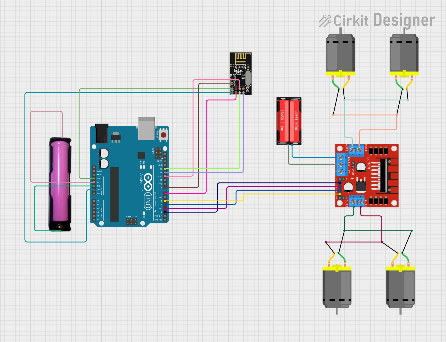
This circuit is designed to control multiple DC motors using an Arduino UNO as the main microcontroller. It includes an L298N DC motor driver to handle the motor control operations, an NRF24L01 module for wireless communication, and a power supply consisting of an 18650 Li-Ion battery and its holder. The Arduino UNO is responsible for interfacing with the NRF24L01 module and the L298N motor driver, sending control signals to the motors.
Component List
Arduino UNO
- Microcontroller board based on the ATmega328P
- It has 14 digital input/output pins, 6 analog inputs, a 16 MHz quartz crystal, a USB connection, a power jack, an ICSP header, and a reset button.
L298N DC Motor Driver
- A module that can control up to two DC motors with independent speed and direction control
- It is capable of driving a current of up to 2A per channel.
NRF24L01
- A 2.4GHz wireless transceiver module
- It has configurable data rates and low power consumption features.
18650 Li-Ion Battery
- A rechargeable battery providing a nominal voltage typically around 3.7V
- Used as a power source for the motor driver.
18650 Battery Holder
- A holder for the 18650 Li-Ion battery
- It provides convenient access to the battery terminals for power supply purposes.
DC Motors
- Four motors that convert electrical energy into mechanical rotation
- Each motor has two terminals for power connection.
Wiring Details
Arduino UNO
3.3Vconnected to NRF24L01VCC (3V)5Vconnected to 18650 battery holderVCCGNDconnected to 18650 battery holderGNDand NRF24L01GNDD13connected to NRF24L01SCKD12connected to NRF24L01MISOD11connected to NRF24L01MOSID8connected to NRF24L01CSND7connected to NRF24L01CED5connected to L298NIN4D4connected to L298NIN3D3connected to L298NIN2D2connected to L298NIN1
L298N DC Motor Driver
OUT1andOUT2connected to two DC MotorsOUT3andOUT4connected to two other DC Motors12Vconnected to 18650 Li-Ion batteryPositiveGNDconnected to 18650 Li-Ion batteryNegative
NRF24L01
VCC (3V)connected to Arduino UNO3.3VGNDconnected to Arduino UNOGNDSCKconnected to Arduino UNOD13MISOconnected to Arduino UNOD12MOSIconnected to Arduino UNOD11CSNconnected to Arduino UNOD8CEconnected to Arduino UNOD7
18650 Li-Ion Battery
Positiveconnected to L298N12VNegativeconnected to L298NGND
18650 Battery Holder
VCCconnected to Arduino UNO5VGNDconnected to Arduino UNOGND
DC Motors
- Two motors connected to L298N
OUT1andOUT2 - Two motors connected to L298N
OUT3andOUT4
Documented Code
Arduino UNO Code (sketch.ino)
void setup() {
  // put your setup code here, to run once:

}

void loop() {
  // put your main code here, to run repeatedly:

}
Additional Notes (documentation.txt)
No additional code documentation was provided.