
Arduino Nano Controlled Wireless Joystick Interface with LCD Feedback
View and Edit Project In Cirkit Designer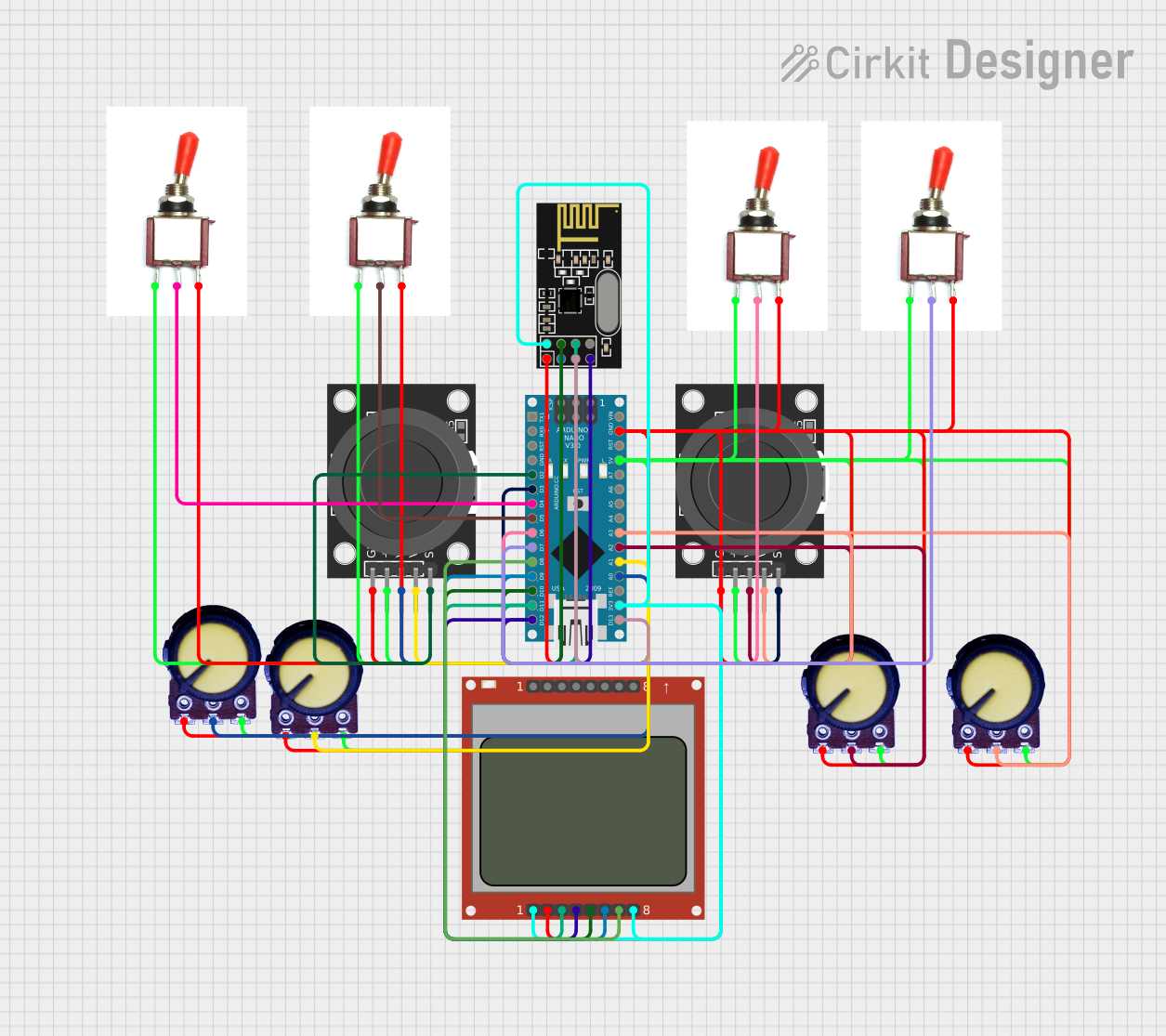
Circuit Documentation
Summary
This circuit integrates various components controlled by an Arduino Nano microcontroller. It includes input devices such as dual-axis joystick modules and potentiometers, output devices like a Nokia 5110 LCD, and a wireless communication module, the NRF24L01. The circuit is designed to capture user inputs through the joysticks, potentiometers, and toggle switches, display information on the LCD, and potentially communicate wirelessly using the NRF24L01 module.
Component List
Arduino Nano
- Microcontroller board based on the ATmega328P
- It has a variety of digital and analog I/O pins.
NRF24L01
- A wireless transceiver module that operates in the 2.4 GHz band.
- It is used for wireless communication between devices.
KY-023 Dual Axis Joystick Module (x2)
- An input device that provides two analog axes and a digital switch.
- It is typically used for directional input in two dimensions.
Toggle Switch (x4)
- An electrical switch that is manually actuated by a mechanical lever, handle, or rocking mechanism.
- It is used to control the flow of electricity in a circuit.
Potentiometer (x4)
- A three-terminal resistor with a sliding or rotating contact that forms an adjustable voltage divider.
- It is commonly used to control electrical devices such as volume controls on audio equipment.
Nokia 5110 LCD
- A small graphic LCD screen for displaying text, images, and shapes.
- It is used for visual output in the circuit.
Wiring Details
Arduino Nano
- Digital pins D2 to D7 are connected to various switches and joystick switches.
- Digital pins D8 to D13 are used for interfacing with the Nokia 5110 LCD and NRF24L01 module.
- Analog pins A0 to A3 are connected to potentiometers and joystick axes.
- The 5V and GND pins provide power to the switches, potentiometers, and joysticks.
- The 3V3 pin powers the Nokia 5110 LCD and NRF24L01 module.
NRF24L01
- Connected to the Arduino Nano via SPI (MOSI, MISO, SCK) and digital pins for CE and CSN.
- Powered by the 3.3V output from the Arduino Nano.
KY-023 Dual Axis Joystick Module
- The VRx and VRy pins are connected to the analog inputs on the Arduino Nano to read the joystick position.
- The SW pin is connected to a digital input to read the joystick button state.
- Powered by the 5V output from the Arduino Nano.
Toggle Switch
- The Sig pin is connected to a digital input on the Arduino Nano to read the switch state.
- Powered by the 5V output from the Arduino Nano.
Potentiometer
- The Output pin is connected to an analog input on the Arduino Nano to read the voltage level.
- Powered by the 5V output from the Arduino Nano.
Nokia 5110 LCD
- The SCLK, DN(MOSI), D/C, SCE, and RST pins are connected to digital pins on the Arduino Nano for control.
- The LED pin is powered by the 3.3V output from the Arduino Nano for backlight.
- Powered by the 3.3V output from the Arduino Nano.
Documented Code
void setup() {
  // put your setup code here, to run once:

}

void loop() {
  // put your main code here, to run repeatedly:

}
The provided code is a template with empty setup() and loop() functions, which are the entry points for Arduino code. The setup() function is called once when the program starts and is used to initialize settings. The loop() function runs repeatedly, allowing the program to change and respond. Users will need to fill in these functions with their specific logic to control the circuit's components based on the wiring details provided.