
Arduino-Controlled Light and Sound System with Laser Emitter
View and Edit Project In Cirkit Designer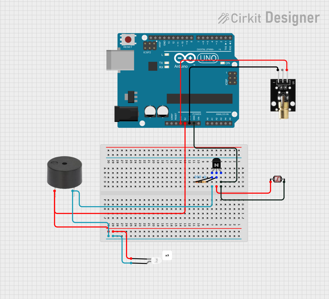
Circuit Documentation
Summary of the Circuit
This circuit is designed around an Arduino UNO microcontroller and includes various components such as an NPN transistor, a resistor, a photocell (LDR), a buzzer, a KY-008 laser emitter, and an LED. The circuit appears to be a sensor-actuator system where the photocell detects light levels, which may then influence the behavior of the buzzer, LED, and laser emitter. The NPN transistor may be used as a switch or amplifier in the circuit. The Arduino UNO serves as the central processing unit, controlling the various components based on the programmed logic.
Component List
Arduino UNO
- Microcontroller board based on the ATmega328P
- It has 14 digital input/output pins, 6 analog inputs, a 16 MHz quartz crystal, a USB connection, a power jack, an ICSP header, and a reset button.
NPN Transistor (EBC)
- A bipolar junction transistor with emitter, base, and collector pins.
- Commonly used for switching and amplification purposes.
Resistor
- A passive two-terminal electrical component that implements electrical resistance as a circuit element.
- Resistance: 200 Ohms
Photocell (LDR)
- A light-dependent resistor whose resistance decreases with increasing incident light intensity.
- It can be used as a light sensor.
Buzzer
- An electromechanical component that can be used to make noise or play tones.
KY-008 Laser Emitter
- A module that emits a small intense beam of light in the laser spectrum.
LED: Two Pin (white)
- A basic light-emitting diode that emits white light when powered.
Wiring Details
Arduino UNO
GNDconnected to the collector of the NPN transistor and the GND pin of the KY-008 Laser Emitter.5Vconnected to the buzzer PIN and the cathode of the LED.3.3Vconnected to the SIG pin of the KY-008 Laser Emitter.
NPN Transistor (EBC)
Collectorconnected to the GND of the Arduino UNO.Baseconnected to the pin 0 of the Photocell (LDR) through a 200 Ohm resistor.Emitterconnected to the GND pin of the buzzer and the anode of the LED.
Resistor
Pin1connected to the emitter of the NPN transistor.Pin2connected to the base of the NPN transistor and pin 0 of the Photocell (LDR).
Photocell (LDR)
Pin 0connected to the base of the NPN transistor through a 200 Ohm resistor.Pin 1connected to the collector of the NPN transistor.
Buzzer
PINconnected to the 5V of the Arduino UNO.GNDconnected to the emitter of the NPN transistor.
KY-008 Laser Emitter
SIGconnected to the 3.3V of the Arduino UNO.GNDconnected to the GND of the Arduino UNO.
LED: Two Pin (white)
Anodeconnected to the emitter of the NPN transistor.Cathodeconnected to the 5V of the Arduino UNO.
Documented Code
Arduino UNO Code (sketch.ino)
void setup() {
  // put your setup code here, to run once:

}

void loop() {
  // put your main code here, to run repeatedly:

}
Note: The provided code is a template and does not contain any functional logic. It needs to be programmed to control the circuit components based on the desired behavior.