
Arduino UNO Smoke Detector with RGB LED and Buzzer - Battery Powered
View and Edit Project In Cirkit Designer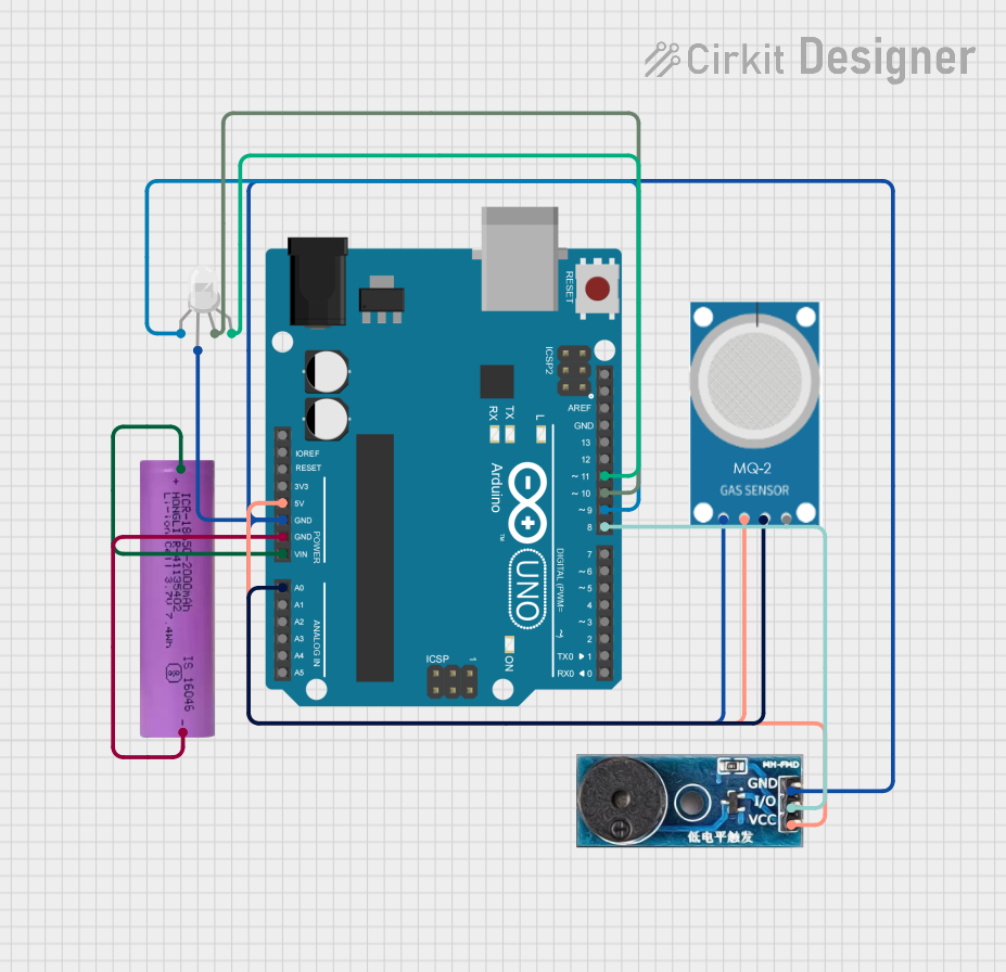
Circuit Documentation
Summary
This circuit is designed to detect smoke levels using an MQ-2 smoke sensor and provide visual and auditory alerts based on the detected smoke concentration. The circuit includes an RGB LED to indicate the smoke level with different colors and a buzzer to sound an alarm when high smoke levels are detected. The system is powered by a Li-ion battery and controlled by an Arduino UNO microcontroller.
Component List
MQ-2 Smoke Sensor
- Description: A sensor used to detect smoke and gas levels.
- Pins: GND, VCC, ANALOG, Digital
Buzzer Module
- Description: A module that produces sound when activated.
- Pins: GND, Vcc, I/O
RGB LED (Wokwi compatible)
- Description: An LED that can emit red, green, and blue light.
- Pins: R, COM, G, B
Li-ion battery 18650-2000mAh 3.7V 7.4WH
- Description: A rechargeable battery used to power the circuit.
- Pins: +, -
Arduino UNO
- Description: A microcontroller board used to control the circuit.
- Pins: UNUSED, IOREF, Reset, 3.3V, 5V, GND, Vin, A0, A1, A2, A3, A4, A5, SCL, SDA, AREF, D13, D12, D11, D10, D9, D8, D7, D6, D5, D4, D3, D2, D1, D0
Wiring Details
MQ-2 Smoke Sensor
- GND connected to Arduino UNO GND
- VCC connected to Arduino UNO 5V
- ANALOG connected to Arduino UNO A0
Buzzer Module
- GND connected to Arduino UNO GND
- Vcc connected to Arduino UNO 5V
- I/O connected to Arduino UNO D8
RGB LED (Wokwi compatible)
- R connected to Arduino UNO D9
- COM connected to Arduino UNO GND
- G connected to Arduino UNO D10
- B connected to Arduino UNO D11
Li-ion battery 18650-2000mAh 3.7V 7.4WH
- + connected to Arduino UNO Vin
- - connected to Arduino UNO GND
Code Documentation
#define smokeSensor A0      // Smoke sensor connected to A0
#define buzzer 8             // Buzzer connected to D8
#define redLED 9             // Red LED pin
#define greenLED 10          // Green LED pin
#define blueLED 11           // Blue LED pin

int threshold;             // Threshold value for smoke detection

void setup() {
  pinMode(smokeSensor, INPUT);
  pinMode(buzzer, OUTPUT);
  pinMode(redLED, OUTPUT);
  pinMode(greenLED, OUTPUT);
  pinMode(blueLED, OUTPUT);
  Serial.begin(9600);

  calibrateSensor();       // Calibrate smoke sensor
}

void loop() {
  int smokeValue = analogRead(smokeSensor);

  Serial.print("Smoke Value: ");
  Serial.println(smokeValue);

  if (smokeValue > threshold + 100) {
    // High danger level
    digitalWrite(buzzer, HIGH);
    setRGB(255, 0, 0); // Red
  } else if (smokeValue > threshold) {
    // Moderate level
    digitalWrite(buzzer, LOW);
    setRGB(255, 255, 0); // Yellow
  } else {
    // Safe level
    digitalWrite(buzzer, LOW);
    setRGB(0, 255, 0); // Green
  }

  delay(2000);  // Adjust delay as needed
}

void setRGB(int r, int g, int b) {
  analogWrite(redLED, r);
  analogWrite(greenLED, g);
  analogWrite(blueLED, b);
}

void calibrateSensor() {
  int baseline = 0;
  for (int i = 0; i < 100; i++) {
    baseline += analogRead(smokeSensor);
    delay(50);
  }
  threshold = baseline / 100 + 50; // Adjust buffer as needed
  Serial.println("Calibrated threshold: " + String(threshold));
}
This code initializes the pins for the smoke sensor, buzzer, and RGB LED. It reads the smoke level from the MQ-2 sensor and compares it to a calibrated threshold. Depending on the smoke level, it activates the buzzer and sets the RGB LED to different colors to indicate the level of danger. The calibrateSensor function is used to determine the baseline smoke level and set an appropriate threshold.