
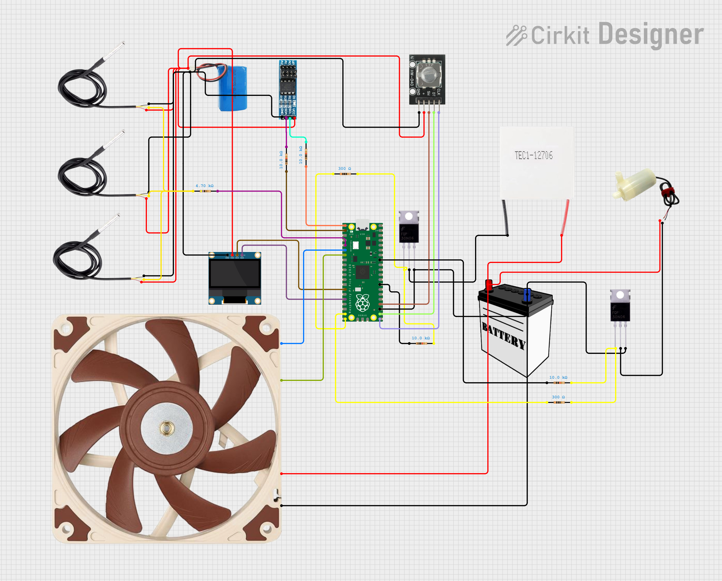
Circuit Documentation
Summary
This document provides a detailed overview of a circuit designed to interface various components with a Raspberry Pi Pico microcontroller. The circuit includes a Peltier Module, an external EEPROM, a mini water pump, an OLED display, MOSFETs, resistors, temperature sensors (DS18B20), a rotary encoder, a 12V PWM fan, and power sources (5V and 12V batteries). The Raspberry Pi Pico controls these components, which are interconnected through a series of electrical nets. The circuit is designed to manage temperature control, data storage, user input, and display information.
Component List
Microcontroller
- Raspberry Pi Pico: A microcontroller board based on the RP2040 microcontroller chip.
Power Sources
- 12V Battery: Provides power to the 12V components in the circuit.
- 5V Battery: Supplies power to the 5V components.
Sensors and Modules
- Peltier Module: A thermoelectric device used for heating or cooling.
- AT24C256 External EEPROM: A memory chip used for storing data.
- DS18B20: A digital temperature sensor.
Actuators
- 5V Mini Water Pump: An actuator for pumping water.
- 12V PWM Fan (120mm): A fan with PWM control for cooling.
Display
- 0.96" OLED: A small display for showing information.
Input Devices
- HW-040 Rotary Encoder: An input device for user interaction.
Discrete Components
- Mosfet: A type of transistor used for switching electronic signals.
- Resistor: A passive two-terminal electrical component that implements electrical resistance.
Wiring Details
Raspberry Pi Pico
- Pin 1: Connected to a 10kΩ resistor.
- Pin 2: Connected to a 10kΩ resistor.
- Pin 5: Connected to a 4.7kΩ resistor.
- Pin 6: Connected to the PWM pin of the 12V PWM Fan.
- Pin 7: Connected to the TACH pin of the 12V PWM Fan.
- Pin 14: Connected to the SCK pin of the 0.96" OLED.
- Pin 16: Connected to the SDA pin of the 0.96" OLED.
- Pin 19: Connected to a 300Ω resistor.
- Pin 20: Connected to a 300Ω resistor.
- Pin 21: Connected to the CLK pin of the HW-040 Rotary Encoder.
- Pin 22: Connected to the DT pin of the HW-040 Rotary Encoder.
- Pin 23: Connected to the ground of the 12V Battery, the source pins of two MOSFETs, and the ground pins of other components.
- Pin 24: Connected to the SW pin of the HW-040 Rotary Encoder.
- Pin 28: Connected to a 10kΩ resistor.
- Pin 33: Connected to a 10kΩ resistor.
Peltier Module
- Negative: Connected to the drain of a MOSFET.
- Positive: Connected to the VCC of the 12V Battery.
AT24C256 External EEPROM
- VCC: Connected to the positive of the 5V Battery.
- SCL: Connected to a 10kΩ resistor.
- SDA: Connected to a 10kΩ resistor.
- GND: Connected to the negative of the 5V Battery.
5V Mini Water Pump
- Positive Pin: Connected to the VCC of the 12V Battery.
- Negative Pin: Connected to the drain of a MOSFET.
0.96" OLED
- GND: Connected to the negative of the 5V Battery.
- VDD: Connected to the positive of the 5V Battery.
- SCK: Connected to Pin 14 of the Raspberry Pi Pico.
- SDA: Connected to Pin 16 of the Raspberry Pi Pico.
Mosfet
- Gate: Connected to a 10kΩ resistor and to the Raspberry Pi Pico for control.
- Drain: Connected to the negative of the Peltier Module and the negative pin of the 5V Mini Water Pump.
- Source: Connected to the ground of the 12V Battery.
Resistor
- Various resistors with values of 300Ω, 4.7kΩ, and 10kΩ are used for pull-ups, pull-downs, and current limiting.
DS18B20
- Signal: Connected to a 4.7kΩ resistor.
- GND: Connected to the negative of the 5V Battery.
- VCC: Connected to the positive of the 5V Battery.
HW-040 Rotary Encoder
- GND: Connected to the negative of the 5V Battery.
- +: Connected to the positive of the 5V Battery.
- SW: Connected to Pin 24 of the Raspberry Pi Pico.
- DT: Connected to Pin 22 of the Raspberry Pi Pico.
- CLK: Connected to Pin 21 of the Raspberry Pi Pico.
12V PWM Fan (120mm)
- GND: Connected to the ground of the 12V Battery.
- +12V: Connected to the VCC of the 12V Battery.
- TACH: Connected to Pin 7 of the Raspberry Pi Pico.
- PWM: Connected to Pin 6 of the Raspberry Pi Pico.
Documented Code
Raspberry Pi Pico Code (sketch.ino)
void setup() {
  // put your setup code here, to run once:

}

void loop() {
  // put your main code here, to run repeatedly:

}
Note: The provided code is a template and does not include specific functionality. It should be populated with the necessary setup and loop code to control the connected components based on the circuit design.