Cirkit Designer
Your all-in-one circuit design IDE
Home /
Project Documentation
Arduino UNO-Based Automation System with IR Sensor and Relay Control
Circuit Documentation
Summary of the Circuit
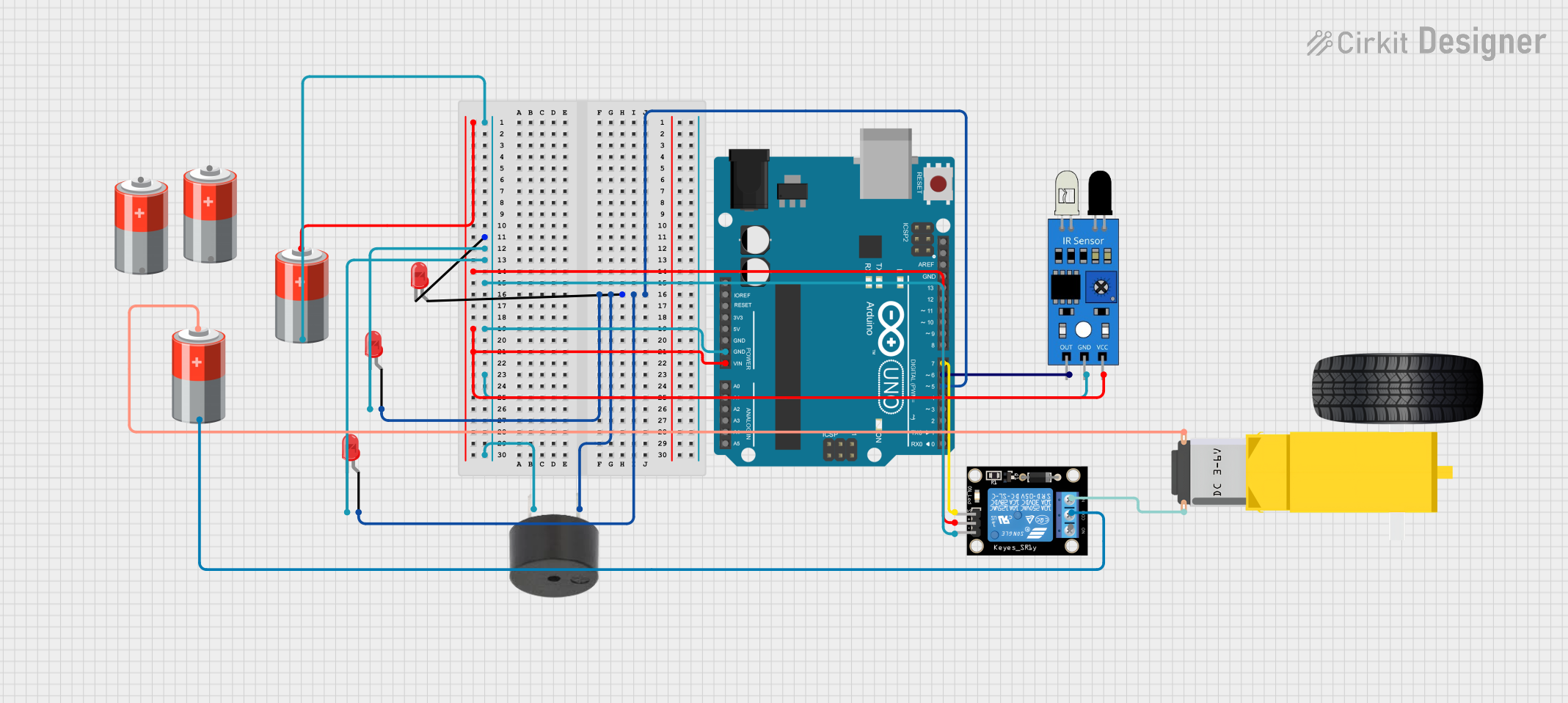
This circuit is designed to interface an Arduino UNO with various components including an IR sensor, a buzzer, a KY-019 Relay module, multiple LEDs, a gearmotor, and power sources. The Arduino UNO acts as the central controller, managing input from the IR sensor and controlling the state of the LEDs, the buzzer, and the relay, which in turn controls the gearmotor. The circuit is powered by 5V batteries connected to the components requiring power.
Component List
Arduino UNO
- Microcontroller board based on the ATmega328P
- It has 14 digital input/output pins, 6 analog inputs, a 16 MHz quartz crystal, a USB connection, a power jack, an ICSP header, and a reset button.
IR Sensor
- An infrared sensor capable of detecting obstacles in its proximity
- Typically has a digital output pin that goes high when an obstacle is detected.
Buzzer
- An electromechanical component that produces sound
- Can be used for audible alerts or alarms.
KY-019 Relay Module 1 Channel
- A relay module that can control high power/high voltage devices
- Has a single channel and can be driven by a low voltage signal like that from a microcontroller.
Gearmotor DC Wheels Right
- A DC motor combined with a gearbox to increase torque
- Used to drive wheels or other mechanical systems.
LED: Two Pin (Red)
- A basic red light-emitting diode
- Has an anode and cathode for simple on/off control.
5V Battery
- A power source providing a 5V output
- Used to power the components in the circuit.
Wiring Details
Arduino UNO
Vinconnected to the positive terminal of the 5V BatteryGNDconnected to the negative terminal of the 5V BatteryD5connected to the anodes of the LEDs and the positive pin of the buzzerD7connected to theSpin of the KY-019 Relay moduleD6connected to theoutpin of the IR sensor
IR Sensor
vccconnected to the positive terminal of the 5V Batterygndconnected to the negative terminal of the 5V Batteryoutconnected toD6on the Arduino UNO
Buzzer
PINconnected toD5on the Arduino UNOGNDconnected to the negative terminal of the 5V Battery
KY-019 Relay Module 1 Channel
5Vconnected to the positive terminal of the 5V BatteryGNDconnected to the negative terminal of the 5V BatterySconnected toD7on the Arduino UNONCconnected toPIN2of the Gearmotor DC Wheels RightCOMconnected to the negative terminal of a separate 5V Battery
Gearmotor DC Wheels Right
PIN1connected to the positive terminal of a separate 5V BatteryPIN2connected to theNCpin of the KY-019 Relay module
LED: Two Pin (Red)
anodeof each LED connected toD5on the Arduino UNOcathodeof each LED connected to the negative terminal of the 5V Battery
5V Battery
+terminal connected toVinon the Arduino UNO,5Von the KY-019 Relay module, andvccon the IR sensor-terminal connected toGNDon the Arduino UNO,GNDon the KY-019 Relay module,gndon the IR sensor,cathodeon each LED, andGNDon the buzzer
Documented Code
sketch.ino
void setup() {
  // put your setup code here, to run once:

}

void loop() {
  // put your main code here, to run repeatedly:

}
documentation.txt
(No additional documentation provided for the code)
This concludes the documentation for the provided circuit design. The circuit is designed to be powered by 5V batteries and controlled by the Arduino UNO, which interacts with the IR sensor, LEDs, buzzer, and relay module to perform its intended functions.