
Arduino-Controlled Relay System with PIR and IR Sensors for Automated Lighting and Fan Operation
View and Edit Project In Cirkit Designer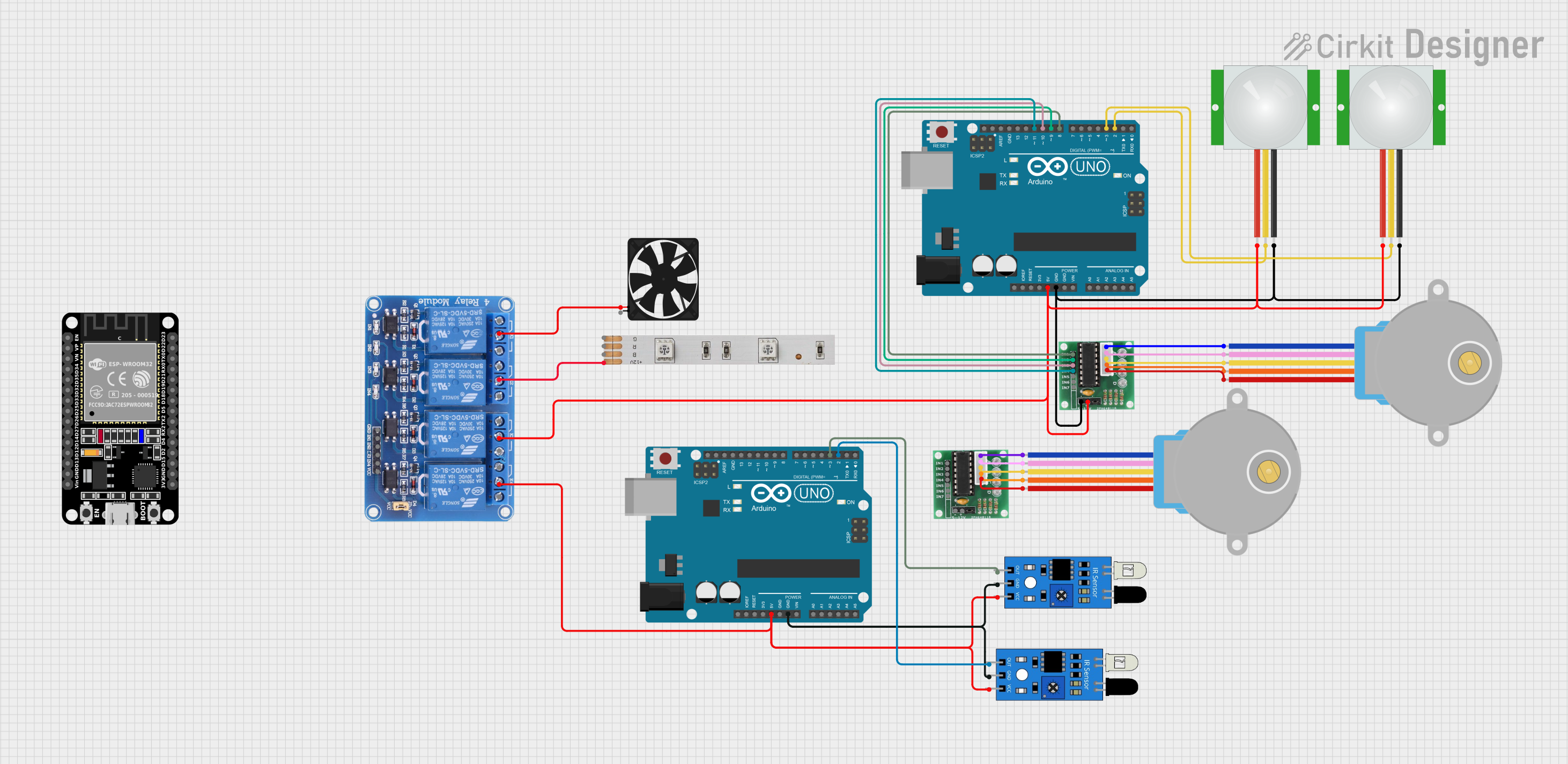
Circuit Documentation
Summary
The circuit in question is a complex system that integrates various components including relays, sensors, a microcontroller, a stepper motor, and an LED strip. The primary control unit is an Arduino UNO microcontroller, which interfaces with a ULN2003 driver to control a 28BYJ-48 stepper motor. The circuit also includes PIR sensors for motion detection and IR sensors for object detection. A relay module is used to switch higher power loads, such as a fan and an LED strip. The system is designed to operate on a 5V supply for logic components and may require a 12V supply for the LED strip.
Component List
Relay 4 Channel 5v
- Description: A 4-channel relay module capable of controlling higher power loads.
- Pins: GND, IN1, IN2, IN3, IN4, VCC, COM1, COM2, COM3, COM4, NO1, NO2, NO3, NO4, NC1, NC2, NC3, NC4
LED Strip
- Description: A strip of LEDs that operates at 12V.
- Pins: B, +12V, R, G
Fan
- Description: A 5V fan used for cooling purposes.
- Pins: GND, 5V
Arduino UNO
- Description: A microcontroller board based on the ATmega328P.
- Pins: UNUSED, IOREF, Reset, 3.3V, 5V, GND, Vin, A0, A1, A2, A3, A4, A5, SCL, SDA, AREF, D13, D12, D11, D10, D9, D8, D7, D6, D5, D4, D3, D2, D1, D0
ULN 2003
- Description: A 7-channel Darlington array used for driving high-current loads.
- Pins: IN1, IN2, IN3, IN4, IN5, IN6, IN7, GND, +, COIL1, COIL2, COIL3, COIL4, COIL5
PIR Sensor
- Description: A passive infrared sensor used for motion detection.
- Pins: VDD, SIG, GND
ESP32 (30 pin)
- Description: A microcontroller with Wi-Fi and Bluetooth capabilities.
- Pins: EN, VP, VN, D34, D35, D32, D33, D25, D26, D27, D14, D12, D13, GND, Vin, D23, D22, TX0, RX0, D21, D19, D18, D5, TX2, RX2, D4, D2, D15, 3V3
28BYJ-48 Stepper Motor
- Description: A small, 5-wire, unipolar stepper motor.
- Pins: BLUE, PINK, YELLOW, ORANGE, RED
IR Sensor
- Description: An infrared sensor used for object detection.
- Pins: out, gnd, vcc
Wiring Details
Relay 4 Channel 5v
- COM1 connected to Fan (5V)
- COM2 connected to LED Strip (+12V)
- COM3 connected to Arduino UNO (5V), ULN 2003 (+), and PIR Sensors (VDD)
- COM4 connected to IR Sensors (vcc) and Arduino UNO (5V)
LED Strip
- +12V connected to Relay 4 Channel 5v (COM2)
Fan
- 5V connected to Relay 4 Channel 5v (COM1)
Arduino UNO
- 5V connected to Relay 4 Channel 5v (COM3 and COM4)
- GND connected to ULN 2003 (GND) and PIR Sensors (GND)
- D11 connected to ULN 2003 (IN4)
- D10 connected to ULN 2003 (IN3)
- D9 connected to ULN 2003 (IN2)
- D8 connected to ULN 2003 (IN1)
- D3 connected to PIR Sensor (SIG) and IR Sensor (out)
- D2 connected to PIR Sensor (SIG) and IR Sensor (out)
ULN 2003
- IN1 to IN4 connected to Arduino UNO (D8 to D11)
- COIL1 to COIL5 connected to 28BYJ-48 Stepper Motor (BLUE to RED)
- GND connected to Arduino UNO (GND)
-
- connected to Relay 4 Channel 5v (COM3)
PIR Sensor
- VDD connected to Relay 4 Channel 5v (COM3)
- SIG connected to Arduino UNO (D2 and D3)
- GND connected to Arduino UNO (GND)
IR Sensor
- vcc connected to Relay 4 Channel 5v (COM4)
- out connected to Arduino UNO (D2 and D3)
- gnd connected to Arduino UNO (GND)
28BYJ-48 Stepper Motor
- BLUE to RED connected to ULN 2003 (COIL1 to COIL5)
Documented Code
Arduino UNO (Instance 1)
void setup() {
  // put your setup code here, to run once:

}

void loop() {
  // put your main code here, to run repeatedly:

}
Arduino UNO (Instance 2)
void setup() {
  // put your setup code here, to run once:

}

void loop() {
  // put your main code here, to run repeatedly:

}
(Note: The code provided for both instances of the Arduino UNO is a template and does not contain any functional code specific to the circuit's operation. Additional code would be required to control the components as per the circuit design.)