Pushbutton-Controlled LED Circuit with Capacitor Smoothing
Circuit Documentation
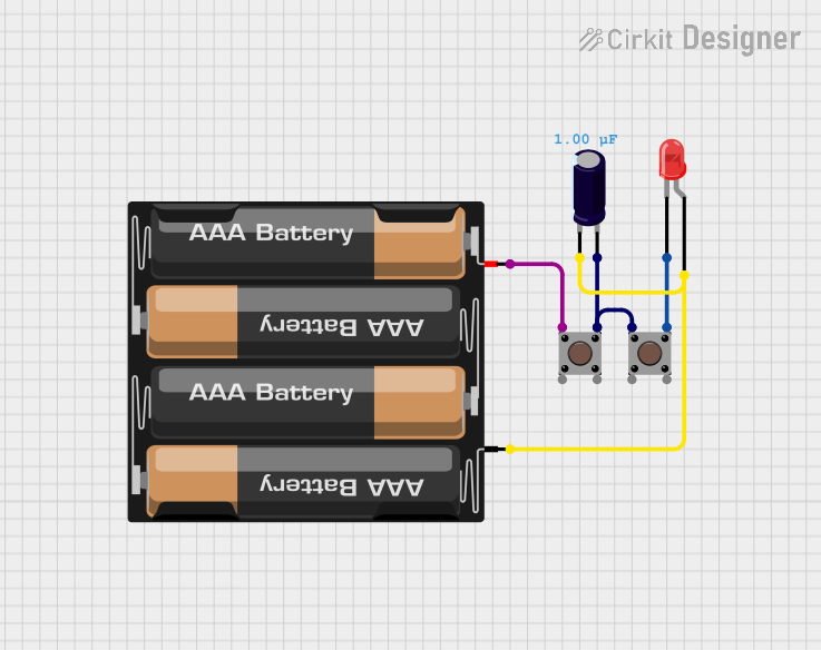
Summary of the Circuit
The circuit described by the provided inputs consists of a simple control and indication system. It includes two pushbuttons, a red LED, an electrolytic capacitor, and a 4 x AAA battery mount as the power source. The LED is controlled by the pushbuttons, which likely serve as a toggle or a switch. The capacitor is connected across the power supply and may serve to smooth out voltage fluctuations or provide a debounce function for the pushbuttons. The absence of a microcontroller in the provided code list indicates that this circuit operates purely on hardware logic without any programmable control.
Component List
LED: Two Pin (red)
- Description: A red LED with two pins: anode and cathode.
- Purpose: To provide visual indication when powered.
Pushbutton
- Description: A standard pushbutton with four pins: two input pins and two output pins.
- Purpose: To control the flow of current in the circuit, likely used to turn the LED on and off.
Electrolytic Capacitor
- Description: A capacitor with a specified capacitance of 1 microfarad (0.000001 Farads).
- Purpose: To stabilize the voltage in the circuit, potentially to debounce the pushbutton signal or filter noise.
4 x AAA Battery Mount
- Description: A battery mount for four AAA batteries, providing a power source for the circuit.
- Purpose: To supply electrical power to the circuit components.
Wiring Details
LED: Two Pin (red)
- Cathode: Connected to the output of one pushbutton.
- Anode: Connected to the negative terminal of the electrolytic capacitor and the negative terminal of the 4 x AAA battery mount.
Pushbutton (First Instance)
- Pin 3 (out): Connected to the cathode of the red LED.
- Pin 1 (in): Connected to the positive terminal of the electrolytic capacitor and the output of the second pushbutton.
Pushbutton (Second Instance)
- Pin 3 (out): Connected to the input of the first pushbutton.
- Pin 1 (in): Connected to the positive terminal of the 4 x AAA battery mount.
Electrolytic Capacitor
- Negative (-) Terminal: Connected to the anode of the red LED and the negative terminal of the 4 x AAA battery mount.
- Positive (+) Terminal: Connected to the input of the first pushbutton and the output of the second pushbutton.
4 x AAA Battery Mount
- Negative (-) Terminal: Connected to the anode of the red LED and the negative terminal of the electrolytic capacitor.
- Positive (+) Terminal: Connected to the input of the second pushbutton.
Documented Code
No code has been provided for any microcontrollers in the circuit. This section is not applicable as the circuit operates without programmable control.
This documentation provides an overview of the circuit's components and their interconnections. It should be noted that the actual functionality of the pushbuttons in relation to the LED cannot be fully determined without additional context or a schematic diagram.