
Arduino Nano Traffic Light System with IR Sensors and Wi-Fi Connectivity
View and Edit Project In Cirkit Designer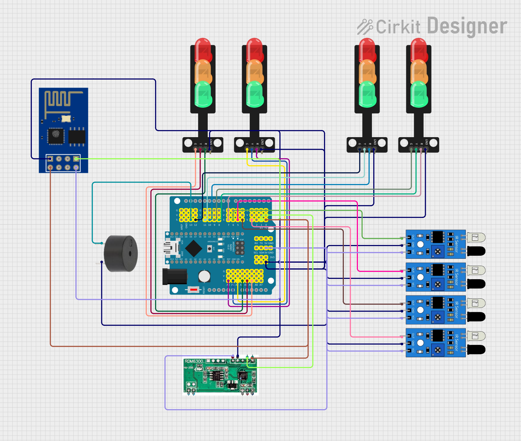
Circuit Documentation
Summary
This circuit is designed to control a set of traffic lights and IR sensors using an Arduino Nano microcontroller mounted on a NANO Shield Board with a power switch. The circuit also includes a buzzer for audio alerts and an ESP-01 module for wireless communication. The traffic lights are controlled through the analog and digital pins of the NANO Shield Board, while the IR sensors detect obstacles and send signals to the microcontroller.
Component List
NANO Shield Board W/ Power Switch
- Description: A shield board for Arduino Nano with a power switch.
- Pins: A0, A1, A2, A3, A4/SDA, A5/SCL, A6, A7, VCC, GND, 3V3, D0/RX, D1/TX, D2, D3 PWM, D4, D5 PWM, D6 PWM, D7, D8, D9 PWM, D10 PWM/SS, D11 PWM/MOSI, D12/MISO, D13/SCK, AREF, RST, NC, VIN
Arduino Nano
- Description: A small, complete, and breadboard-friendly board based on the ATmega328P.
- Pins: D1/TX, D0/RX, RESET, GND, D2, D3, D4, D5, D6, D7, D8, D9, D10, D11/MOSI, D12/MISO, VIN, 5V, A7, A6, A5, A4, A3, A2, A1, A0, AREF, 3V3, D13/SCK
Traffic Light
- Description: A traffic light module with red, yellow, and green LEDs.
- Pins: Green, Yellow, Red, GND
IR Sensor
- Description: An infrared sensor module for obstacle detection.
- Pins: out, gnd, vcc
Buzzer
- Description: A simple buzzer for audio alerts.
- Pins: PIN, GND
ESP-01
- Description: A Wi-Fi module based on the ESP8266.
- Pins: GND, GPIO02, GPIO0, RX, VCC, RST, CH_PD, TX
RDM 6300
- Description: An RFID reader module.
- Pins: VCC, GND, RX, TX, ANT 1, ANT 2, LED
Wiring Details
NANO Shield Board W/ Power Switch
- A0: Connected to Red pin of Traffic Light
- A1: Connected to Yellow pin of Traffic Light
- A2: Connected to Green pin of Traffic Light
- A3: Connected to Red pin of Traffic Light
- A4/SDA: Connected to Yellow pin of Traffic Light
- A5/SCL: Connected to Green pin of Traffic Light
- GND: Connected to GND pins of Traffic Lights, IR Sensors, RDM 6300, ESP-01, and Buzzer
- VCC: Connected to VCC pins of IR Sensors, RDM 6300, and ESP-01
- D0/RX: Connected to TX pins of RDM 6300 and ESP-01
- D1/TX: Connected to RX pins of RDM 6300 and ESP-01
- D3 PWM: Connected to out pin of IR Sensor
- D4: Connected to out pin of IR Sensor
- D5 PWM: Connected to out pin of IR Sensor
- D6 PWM: Connected to out pin of IR Sensor
- D7: Connected to Red pin of Traffic Light
- D8: Connected to Yellow pin of Traffic Light
- D9 PWM: Connected to Green pin of Traffic Light
- D10 PWM/SS: Connected to Red pin of Traffic Light
- D11 PWM/MOSI: Connected to Yellow pin of Traffic Light
- D12/MISO: Connected to Green pin of Traffic Light
- D13/SCK: Connected to PIN of Buzzer
Arduino Nano
- D1/TX: Not connected
- D0/RX: Not connected
- RESET: Not connected
- GND: Not connected
- D2: Not connected
- D3: Not connected
- D4: Not connected
- D5: Not connected
- D6: Not connected
- D7: Not connected
- D8: Not connected
- D9: Not connected
- D10: Not connected
- D11/MOSI: Not connected
- D12/MISO: Not connected
- VIN: Not connected
- 5V: Not connected
- A7: Not connected
- A6: Not connected
- A5: Not connected
- A4: Not connected
- A3: Not connected
- A2: Not connected
- A1: Not connected
- A0: Not connected
- AREF: Not connected
- 3V3: Not connected
- D13/SCK: Not connected
Traffic Light
- Red: Connected to A0, A3, D7, D10 PWM/SS of NANO Shield Board
- Yellow: Connected to A1, A4/SDA, D8, D11 PWM/MOSI of NANO Shield Board
- Green: Connected to A2, A5/SCL, D9 PWM, D12/MISO of NANO Shield Board
- GND: Connected to GND of NANO Shield Board
IR Sensor
- out: Connected to D3 PWM, D4, D5 PWM, D6 PWM of NANO Shield Board
- gnd: Connected to GND of NANO Shield Board
- vcc: Connected to VCC of NANO Shield Board
Buzzer
- PIN: Connected to D13/SCK of NANO Shield Board
- GND: Connected to GND of NANO Shield Board
ESP-01
- GND: Connected to GND of NANO Shield Board
- GPIO02: Not connected
- GPIO0: Not connected
- RX: Connected to D1/TX of NANO Shield Board
- VCC: Connected to VCC of NANO Shield Board
- RST: Not connected
- CH_PD: Not connected
- TX: Connected to D0/RX of NANO Shield Board
RDM 6300
- VCC: Connected to VCC of NANO Shield Board
- GND: Connected to GND of NANO Shield Board
- RX: Connected to D1/TX of NANO Shield Board
- TX: Connected to D0/RX of NANO Shield Board
- ANT 1: Not connected
- ANT 2: Not connected
- LED: Not connected
Documented Code
Arduino Nano Code (sketch.ino)
void setup() {
  // put your setup code here, to run once:

}

void loop() {
  // put your main code here, to run repeatedly:

}
Documentation (documentation.txt)
This documentation provides a comprehensive overview of the circuit, including a summary, detailed component list, wiring details, and the code used in the microcontroller.