Cirkit Designer
Your all-in-one circuit design IDE
Home /
Project Documentation
Arduino UNO R4 WiFi Controlled Servo Motor with Diode Protection
Circuit Documentation
Summary of the Circuit
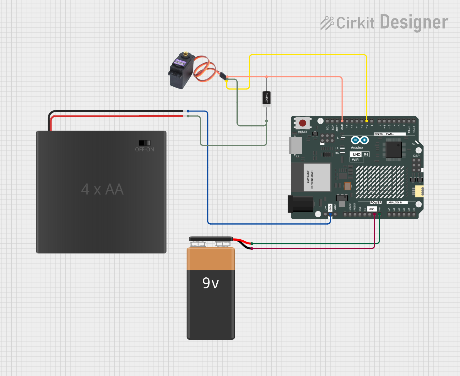
This circuit is designed to interface an Arduino UNO R4 WiFi with a servo motor (MG996R) and power sources (4xAA battery pack and a 9V battery). The servo is controlled by the Arduino, which is powered by the 9V battery. The servo motor is powered by the 4xAA battery pack, with a 1N4007 diode providing reverse polarity protection.
Component List
Arduino UNO R4 WiFi
- Description: A microcontroller board based on the ATmega328, with integrated WiFi capabilities.
- Purpose: Acts as the central controller for the circuit, executing the embedded code to control the servo motor and manage power from the batteries.
- Pins: OFF, GND, VRTC, IIC0_SCL, IIC0_SDA, 3V3, GPIO 41, GPIO 0, GPIO 42, GPIO 43, GPIO 44, BOOT, IOREF, RESET, 5V, VIN, A0, A1, A2, A3, A4, A5, RSPCKA, CIPO, COPI, D0/RX, D1/TX, D2, D3, D4, D5, D6, D7, D8, D9, D10, D11, D12, D13, AREF, SDA, SCL.
4xAA Battery Pack
- Description: A battery holder for four AA batteries, providing a nominal voltage of 6V when batteries are installed.
- Purpose: Supplies power to the servo motor.
MG996R Servo Motor
- Description: A high-torque digital servo motor.
- Purpose: The actuator in the circuit, which is controlled by the Arduino.
9V Battery
- Description: A standard 9V battery.
- Purpose: Provides power to the Arduino UNO R4 WiFi.
1N4007 Rectifier Diode
- Description: A general-purpose rectifier diode with a high maximum current and reverse voltage rating.
- Purpose: Protects the servo motor from potential reverse polarity damage.
Wiring Details
Arduino UNO R4 WiFi
- GND connected to:
- 4xAA battery pack NEG terminal
- 9V battery "-" terminal
- MG996R GND pin
- 1N4007 Rectifier Diode Anode pin
- VIN connected to 9V battery "+" terminal
- D9 connected to MG996R SIG pin
4xAA Battery Pack
- NEG connected to Arduino UNO R4 WiFi GND
- POS connected to:
- MG996R VCC pin
- 1N4007 Rectifier Diode Cathode pin
MG996R Servo Motor
- GND connected to Arduino UNO R4 WiFi GND and 1N4007 Rectifier Diode Anode pin
- VCC connected to 4xAA battery pack POS terminal
- SIG connected to Arduino UNO R4 WiFi D9 pin
9V Battery
- "+" connected to Arduino UNO R4 WiFi VIN pin
- "-" connected to Arduino UNO R4 WiFi GND pin
1N4007 Rectifier Diode
- Anode connected to MG996R GND pin and Arduino UNO R4 WiFi GND pin
- Cathode connected to 4xAA battery pack POS terminal
Documented Code
Arduino UNO R4 WiFi Code (sketch.ino)
void setup() {
  // put your setup code here, to run once:

}

void loop() {
  // put your main code here, to run repeatedly:

}
Note: The provided code is a template and does not contain any functional code to control the servo motor. The user should implement the setup and loop functions to initialize the servo motor and define its behavior.