Arduino-Controlled Relay Switch for Bulb Illumination
Circuit Documentation
Summary of the Circuit
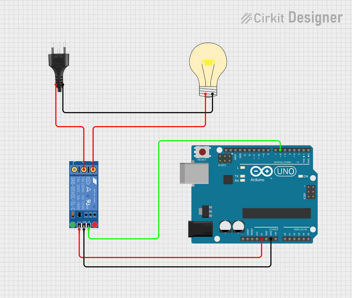
This circuit is designed to control a bulb using an Arduino UNO microcontroller and a KF-301 relay. The relay allows the Arduino to switch the high-power circuit of the bulb on and off. The bulb is connected to a socket that provides the power source. The Arduino controls the relay by sending a signal to it, which in turn, connects or disconnects the bulb from the power source. The control logic is implemented in the embedded code running on the Arduino, which toggles the relay at a 3-second interval, using an inverted logic where a LOW signal activates the relay and a HIGH signal deactivates it.
Component List
Bulb
- Pins: positive, negative
- Description: A standard light bulb that illuminates when powered.
- Purpose: To provide a visual indication of the relay's state (on/off).
Arduino UNO
- Pins: UNUSED, IOREF, Reset, 3.3V, 5V, GND, Vin, A0-A5, SCL, SDA, AREF, D0-D13
- Description: A microcontroller board based on the ATmega328P.
- Purpose: To control the relay and, by extension, the power to the bulb.
KF-301 Relay
- Pins: signal, power, ground, NC, C, NO
- Description: An electromechanical switch that can be controlled by a low-power signal.
- Purpose: To switch the high-power circuit of the bulb on and off.
Socket
- Pins: positive, negative
- Description: A connector that provides a means to connect the bulb to a power source.
- Purpose: To supply power to the bulb when the relay is activated.
Wiring Details
Bulb
- positive connected to KF-301 Relay NO
- negative connected to Socket negative
Arduino UNO
- 5V connected to KF-301 Relay power
- GND connected to KF-301 Relay ground
- D6 connected to KF-301 Relay signal
KF-301 Relay
- signal connected to Arduino UNO D6
- power connected to Arduino UNO 5V
- ground connected to Arduino UNO GND
- NO connected to Bulb positive
- C connected to Socket positive
Socket
- positive connected to KF-301 Relay C
- negative connected to Bulb negative
Documented Code
/*
  Relay Control Sketch
  This sketch controls a relay connected to pin D6 of an Arduino UNO.
  The relay is turned on for 3 seconds and then turned off for 3 seconds in a continuous loop.
  The relay activation is inverted; a LOW signal turns it on, and a HIGH signal turns it off.
*/

int RelayPin = 6; // Define the Arduino pin connected to the relay signal pin

void setup() {
  pinMode(RelayPin, OUTPUT); // Set RelayPin as an output pin
}

void loop() {
  digitalWrite(RelayPin, LOW); // Turn on the relay (inverted logic: LOW means relay on)
  delay(3000);                 // Wait for 3 seconds

  digitalWrite(RelayPin, HIGH); // Turn off the relay (inverted logic: HIGH means relay off)
  delay(3000);                  // Wait for 3 seconds
}
This code is written for the Arduino UNO and is responsible for controlling the KF-301 Relay. The relay is connected to digital pin D6 of the Arduino. The code sets the pin as an output and then enters a loop where it turns the relay on (LOW signal) for 3 seconds, then off (HIGH signal) for another 3 seconds, repeating this cycle indefinitely.