
Arduino Uno R3-Based Security System with Laser Tripwire, GSM Notification, and Motion Detection
View and Edit Project In Cirkit Designer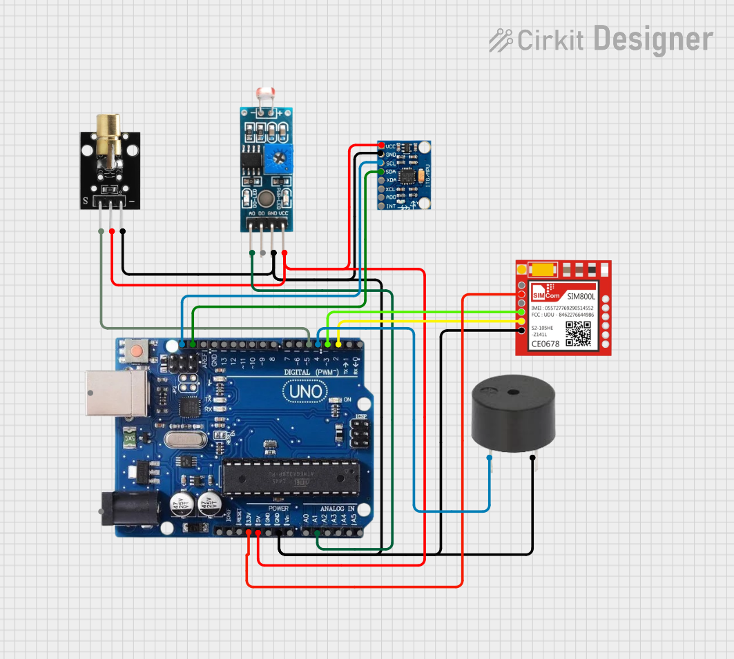
Circuit Documentation
Summary
The circuit in question is designed to interface various components with an Arduino Uno R3 microcontroller. The components include a KY-008 Laser Emitter, a Module LDR (Light Dependent Resistor), a buzzer, a Sim800l GSM module, and an MPU-6050 accelerometer and gyroscope module. The circuit is powered by the Arduino Uno R3, which also provides signal and data connections to the various components. The circuit is intended for applications that require light sensing, motion detection, laser emission, sound alerts, and GSM communication capabilities.
Component List
KY-008 Laser Emitter
- Pins: SIG, 5v, GND
- Description: A module that emits a laser when powered.
Module LDR
- Pins: VCC, GND, DO, AO
- Description: A light-dependent resistor module that changes resistance based on light intensity.
Arduino Uno R3
- Pins: USB Port, Power Jack, Not Connected, IOREF, RESET, 3.3V, 5V, GND, VIN, A0-A5, SCL, SDA, AREF, Digital Pins 0-13
- Description: A microcontroller board based on the ATmega328P, widely used for building digital devices and interactive objects.
Buzzer
- Pins: PIN, GND
- Description: An electronic buzzer for producing sound signals.
Sim800l
- Pins: NET, RST, VCC, RXD, TXD, GND
- Description: A GSM/GPRS module that allows for cellular communication.
MPU-6050
- Pins: VCC, GND, SCL, SDA, XDA, XCL, AD0, INT
- Description: A motion-tracking device with a 3-axis gyroscope and a 3-axis accelerometer.
Wiring Details
KY-008 Laser Emitter
- SIG connected to Arduino Uno R3 Pin 5
- 5v connected to Arduino Uno R3 5V
- GND connected to common ground
Module LDR
- VCC connected to Arduino Uno R3 5V
- GND connected to common ground
- DO (not connected in this circuit)
- AO connected to Arduino Uno R3 Pin A1
Arduino Uno R3
- 5V supplying power to KY-008 Laser Emitter and Module LDR
- 3.3V supplying power to Sim800l
- GND common ground for all components
- Digital Pins 2, 3, 4, 5 used for TXD, RXD, buzzer, and laser emitter respectively
- Analog Pins A1 connected to Module LDR AO
- I2C Pins SCL and SDA connected to MPU-6050 SCL and SDA
Buzzer
- PIN connected to Arduino Uno R3 Pin 4
- GND connected to common ground
Sim800l
- VCC connected to Arduino Uno R3 3.3V
- GND connected to common ground
- RXD connected to Arduino Uno R3 Pin 3
- TXD connected to Arduino Uno R3 Pin 2
- NET, RST (not connected in this circuit)
MPU-6050
- VCC connected to Arduino Uno R3 5V
- GND connected to common ground
- SCL connected to Arduino Uno R3 SCL
- SDA connected to Arduino Uno R3 SDA
- XDA, XCL, AD0, INT (not connected in this circuit)
Documented Code
No code has been provided for the microcontroller. The documentation of the code would typically include setup and loop functions for Arduino sketches, along with any necessary function definitions and library inclusions. Since no code is available, this section cannot be completed. If code becomes available, it should be documented here with explanations of how the code interacts with the connected hardware components.