
Arduino Nano-Based LED Control System with Hall Sensor and IR Receiver
View and Edit Project In Cirkit Designer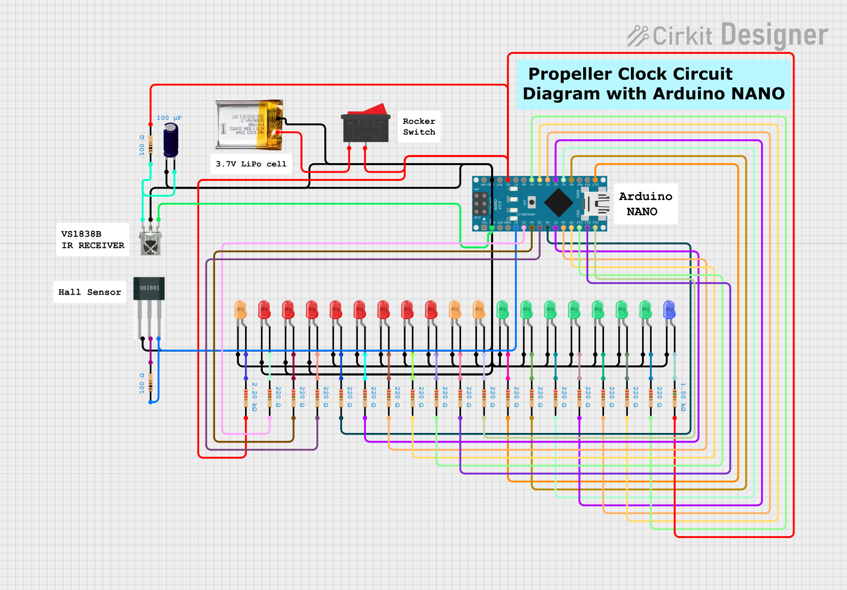
Circuit Documentation
Summary
This circuit consists of multiple LEDs of different colors, resistors, a Hall sensor, an IR receiver, an Arduino Nano microcontroller, a LiPo battery, a rocker switch, and an electrolytic capacitor. The circuit is designed to control the LEDs and read inputs from the Hall sensor and IR receiver using the Arduino Nano. The power is supplied by a 3.7V LiPo battery, and the circuit can be turned on or off using the rocker switch.
Component List
LED: Two Pin (red)
- Pins: cathode, anode
- Description: Red LED
LED: Two Pin (green)
- Pins: cathode, anode
- Description: Green LED
LED: Two Pin (orange)
- Pins: cathode, anode
- Description: Orange LED
LED: Two Pin (blue)
- Pins: cathode, anode
- Description: Blue LED
Hall Sensor
- Pins: -, +, S
- Description: Hall effect sensor
Resistor
- Pins: pin1, pin2
- Description: Resistor
- Properties: Various resistances (220 Ohms, 100 Ohms, 1500 Ohms, 2200 Ohms)
VS1838B IR Receiver
- Pins: OUT, GND, VCC
- Description: IR receiver
Arduino Nano
- Pins: D1/TX, D0/RX, RESET, GND, D2, D3, D4, D5, D6, D7, D8, D9, D10, D11/MOSI, D12/MISO, VIN, 5V, A7, A6, A5, A4, A3, A2, A1, A0, AREF, 3V3, D13/SCK
- Description: Microcontroller
Electrolytic Capacitor
- Pins: -, +
- Description: Capacitor
- Properties: 0.0001 Farads
Rocker Switch
- Pins: 1, 2
- Description: On/Off switch
3.7V LiPo Battery
- Pins: +Ve, GND
- Description: Lithium Polymer battery
Wiring Details
LED: Two Pin (red)
- Anode connected to:
- Resistor pin1 (various resistors)
- Cathode connected to:
- Common ground (GND)
LED: Two Pin (green)
- Anode connected to:
- Resistor pin1 (various resistors)
- Cathode connected to:
- Common ground (GND)
LED: Two Pin (orange)
- Anode connected to:
- Resistor pin1 (various resistors)
- Cathode connected to:
- Common ground (GND)
LED: Two Pin (blue)
- Anode connected to:
- Resistor pin1 (1500 Ohms)
- Cathode connected to:
- Common ground (GND)
Hall Sensor
- - connected to:
- Common ground (GND)
- + connected to:
- Resistor pin2 (220 Ohms)
- S connected to:
- Arduino Nano D2
Resistor
- Pin1 connected to:
- Various LED anodes
- Pin2 connected to:
- Various Arduino Nano pins (D3, D4, D5, D6, D7, D8, D9, D10, D11/MOSI, D12/MISO, A0, A1, A2, A3, A4, A5, D13/SCK)
- Hall Sensor +
- Rocker Switch pin2
VS1838B IR Receiver
- OUT connected to:
- Arduino Nano D0/RX
- GND connected to:
- Common ground (GND)
- VCC connected to:
- Resistor pin1 (100 Ohms)
Arduino Nano
- D0/RX connected to:
- VS1838B IR Receiver OUT
- D2 connected to:
- Hall Sensor S
- D3 connected to:
- Resistor pin2 (220 Ohms)
- D4 connected to:
- Resistor pin2 (220 Ohms)
- D5 connected to:
- Resistor pin2 (220 Ohms)
- D6 connected to:
- Resistor pin2 (220 Ohms)
- D7 connected to:
- Resistor pin2 (220 Ohms)
- D8 connected to:
- Resistor pin2 (220 Ohms)
- D9 connected to:
- Resistor pin2 (220 Ohms)
- D10 connected to:
- Resistor pin2 (220 Ohms)
- D11/MOSI connected to:
- Resistor pin2 (220 Ohms)
- D12/MISO connected to:
- Resistor pin2 (220 Ohms)
- A0 connected to:
- Resistor pin2 (220 Ohms)
- A1 connected to:
- Resistor pin2 (220 Ohms)
- A2 connected to:
- Resistor pin2 (220 Ohms)
- A3 connected to:
- Resistor pin2 (220 Ohms)
- A4 connected to:
- Resistor pin2 (220 Ohms)
- A5 connected to:
- Resistor pin2 (220 Ohms)
- D13/SCK connected to:
- Resistor pin2 (220 Ohms)
- 5V connected to:
- Resistor pin2 (1500 Ohms)
- GND connected to:
- Common ground (GND)
Electrolytic Capacitor
- + connected to:
- VS1838B IR Receiver VCC
- - connected to:
- Common ground (GND)
Rocker Switch
- Pin1 connected to:
- 3.7V LiPo Battery +Ve
- Pin2 connected to:
- Resistor pin2 (2200 Ohms)
- Arduino Nano 5V
3.7V LiPo Battery
- +Ve connected to:
- Rocker Switch pin1
- GND connected to:
- Common ground (GND)
Code Documentation
Arduino Nano Code
void setup() {
  // put your setup code here, to run once:

}

void loop() {
  // put your main code here, to run repeatedly:

}
This code is a basic template for the Arduino Nano. The setup() function is where you initialize your components and settings, and it runs once when the microcontroller is powered on or reset. The loop() function contains the main code that runs repeatedly. You can add your specific logic to control the LEDs, read the Hall sensor, and process the IR receiver signals within these functions.