Wi-Fi Controlled ESP32-Based Robotic Vehicle with Servo Actuation and Ultrasonic Sensing
Circuit Documentation
Summary
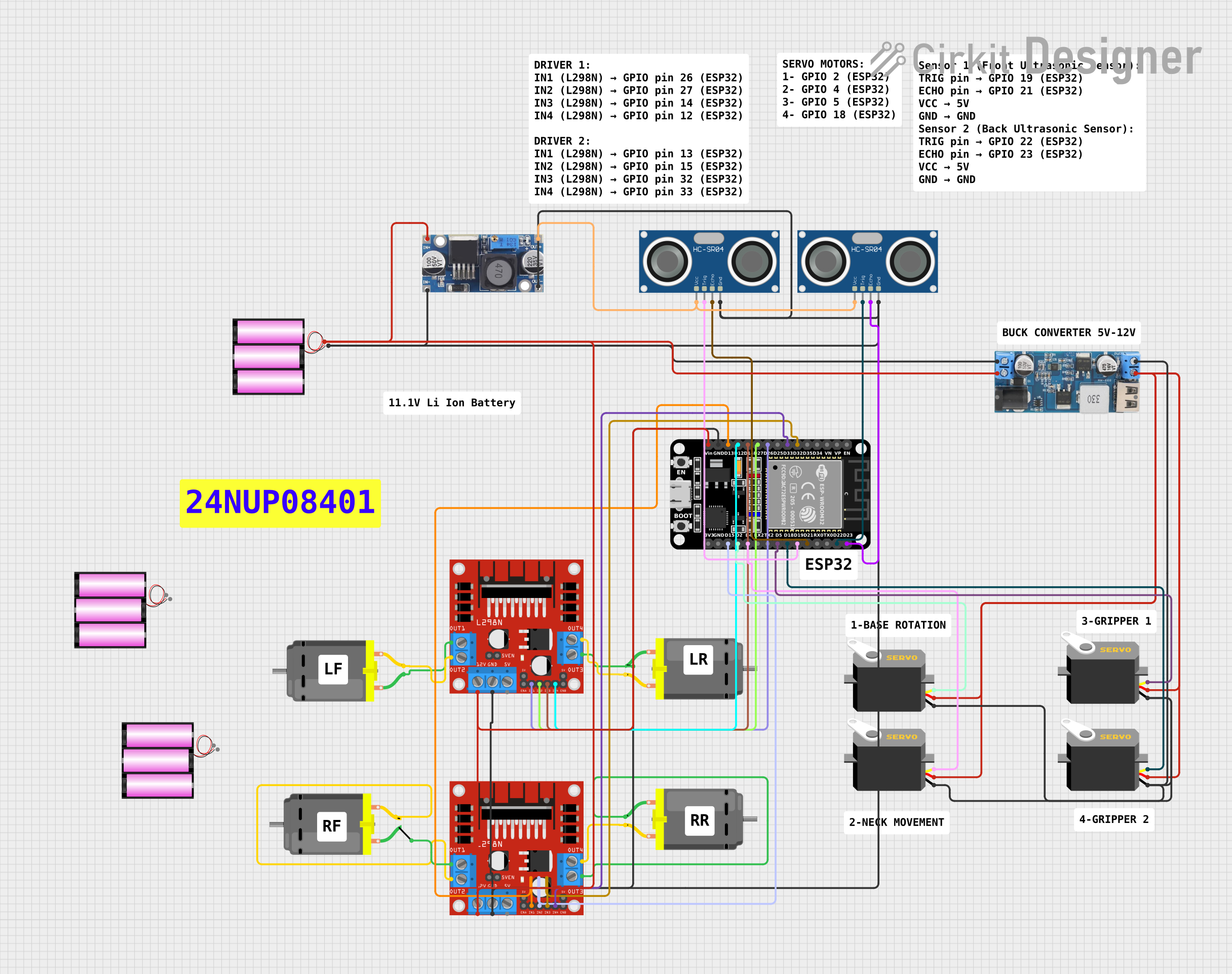
The circuit in question is designed to control multiple DC motors and servos using an ESP32 microcontroller. The ESP32 is programmed to handle motor control through a web server interface, allowing for remote operation. The circuit includes motor drivers to manage the power requirements of the DC motors, ultrasonic sensors for distance measurement, and a step-down power converter to regulate the voltage for the servos and sensors. The system is powered by 12V batteries, and a voltage converter is used to step down the voltage to 5V where necessary.
Component List
Microcontroller
- ESP32 (30 pin): A microcontroller with Wi-Fi capabilities, used as the central processing unit of the circuit to control motors, servos, and read sensors.
Motor Drivers
- L298N DC motor driver: Used to drive the DC motors, providing the necessary current and allowing for direction control.
Motors
- DC Motor: Four instances of DC motors are present in the circuit, controlled by the motor drivers.
Servos
- Servo: Four instances of servos are used, likely for precise angular positioning.
Sensors
- HC-SR04 Ultrasonic Sensor: Two instances of ultrasonic sensors for distance measurement.
Power Components
- 12v to 5v Step Down Power Converter: Converts 12V to 5V to power the servos and potentially other 5V components.
- 48v to 5v: Another voltage converter, possibly for additional 5V power requirements.
- battery 12v: Three instances of 12V batteries to provide power to the circuit.
Wiring Details
ESP32 (30 pin)
- D32, D33: Connected to the L298N motor driver for motor control signals.
- D26, D27, D14, D12, D13, D15: Connected to another L298N motor driver for motor control signals.
- GND: Common ground connection with various components including the step-down converter, ultrasonic sensors, motor drivers, and batteries.
- Vin: Power input connected to the 12V battery and step-down converter.
- D23, D22: Connected to the ECHO and TRIG pins of one HC-SR04 ultrasonic sensor.
- D21, D19: Connected to the ECHO and TRIG pins of another HC-SR04 ultrasonic sensor.
- D18, D5, D4, D2: Control pins for the four servos.
L298N DC motor driver
- IN1, IN2, IN3, IN4: Control inputs from the ESP32 for motor direction.
- OUT1, OUT2, OUT3, OUT4: Outputs connected to the DC motors.
- 12V: Power input from the 12V battery.
- GND: Ground connection.
DC Motor
- pin 1, pin 2: Connected to the outputs of the L298N motor drivers.
Servo
- gnd: Ground connection through the step-down converter.
- vcc: Power input from the step-down converter.
- pulse: Control signal from the ESP32.
HC-SR04 Ultrasonic Sensor
- VCC: Power input from the 48v to 5v converter.
- TRIG, ECHO: Control and signal pins connected to the ESP32.
- GND: Ground connection.
12v to 5v Step Down Power Converter
- VIN 9v-36v, VIN+, VIN-: Input from the 12V battery.
- USB OUTPUT 5V, 5v OUTPUT: 5V power output to servos.
- GND: Ground connection.
battery 12v
- +: Positive terminal connected to the ESP32 Vin and motor drivers.
- -: Negative terminal connected to the common ground.
48v to 5v
- out+, out--: 5V output connected to the ultrasonic sensors.
- in+, in--: Input presumably from a higher voltage source.
Documented Code
#include <WiFi.h>
#include <ESPAsyncWebServer.h>
#include <Servo.h>

// Motor pins (L298N Motor Driver)
const int motor1Pin1 = 26;
const int motor1Pin2 = 27;
const int motor2Pin1 = 14;
const int motor2Pin2 = 12;
const int motor3Pin1 = 13;
const int motor3Pin2 = 15;
const int motor4Pin1 = 32;
const int motor4Pin2 = 33;

// Servo pins
Servo servo1;
Servo servo2;
Servo servo3;
Servo servo4;

const int servo1Pin = 2;
const int servo2Pin = 4;
const int servo3Pin = 5;
const int servo4Pin = 18;

// Wi-Fi credentials
const char *ssid = "YOUR_SSID";
const char *password = "YOUR_PASSWORD";

// Server object
AsyncWebServer server(80);

// Function to stop all motors
void stopMotors() {
  digitalWrite(motor1Pin1, LOW);
  digitalWrite(motor1Pin2, LOW);
  digitalWrite(motor2Pin1, LOW);
  digitalWrite(motor2Pin2, LOW);
  digitalWrite(motor3Pin1, LOW);
  digitalWrite(motor3Pin2, LOW);
  digitalWrite(motor4Pin1, LOW);
  digitalWrite(motor4Pin2, LOW);
}

void setup() {
  // Initialize Serial Monitor
  Serial.begin(115200);

  // Setup motor pins
  pinMode(motor1Pin1, OUTPUT);
  pinMode(motor1Pin2, OUTPUT);
  pinMode(motor2Pin1, OUTPUT);
  pinMode(motor2Pin2, OUTPUT);
  pinMode(motor3Pin1, OUTPUT);
  pinMode(motor3Pin2, OUTPUT);
  pinMode(motor4Pin1, OUTPUT);
  pinMode(motor4Pin2, OUTPUT);

  // Attach servos
  servo1.attach(servo1Pin);
  servo2.attach(servo2Pin);
  servo3.attach(servo3Pin);
  servo4.attach(servo4Pin);

  // Connect to Wi-Fi
  WiFi.begin(ssid, password);
  while (WiFi.status() != WL_CONNECTED) {
    delay(1000);
    Serial.println("Connecting to WiFi...");
  }
  Serial.println("Connected to WiFi");

  // Setup web server routes
  server.on("/", HTTP_GET, [](AsyncWebServerRequest *request) {
    request->send(200, "text/plain", "Control your RC Car");
  });

  // Control routes (adjust as per app logic)
  server.on("/forward", HTTP_GET, [](AsyncWebServerRequest *request) {
    digitalWrite(motor1Pin1, HIGH);
    digitalWrite(motor1Pin2, LOW);
    digitalWrite(motor2Pin1, HIGH);
    digitalWrite(motor2Pin2, LOW);
    digitalWrite(motor3Pin1, HIGH);
    digitalWrite(motor3Pin2, LOW);
    digitalWrite(motor4Pin1, HIGH);
    digitalWrite(motor4Pin2, LOW);
    request->send(200, "text/plain", "Moving Forward");
  });

  server.on("/stop", HTTP_GET, [](AsyncWebServerRequest *request) {
    stopMotors();
    request->send(200, "text/plain", "Stopped");
  });

  server.begin();
}

void loop() {
  // Handle other actions like servo movement in response to app commands
}
This code sets up the ESP32 to control the motors and servos via a web server. It defines the pin connections, initializes the components, and provides a basic web interface for controlling the vehicle's movement. The stopMotors function is used to stop all motors, and the setup function configures the Wi-Fi connection and server routes. The loop function is left empty, as the server handles the asynchronous requests.