
ESP32-Based Smart Home Automation System with Servo Motors and Ultrasonic Sensor
View and Edit Project In Cirkit Designer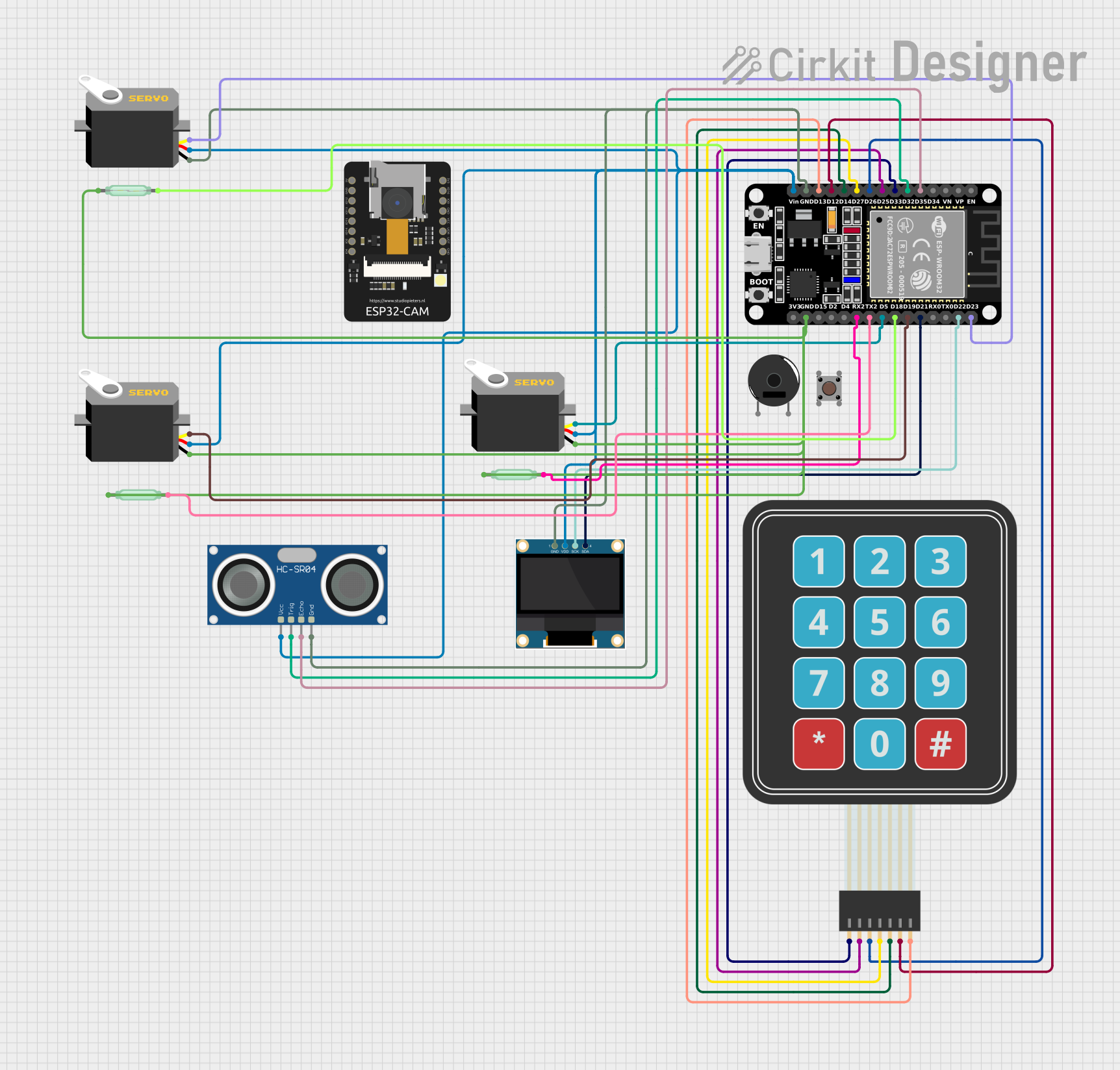
Circuit Documentation
Summary
This document provides a detailed overview of a circuit that includes various components such as servos, pushbuttons, an ESP32 microcontroller, an ultrasonic sensor, an OLED display, a membrane matrix keypad, a piezo buzzer, and reed switches. The circuit is designed to interface these components with the ESP32 microcontroller to perform various tasks.
Component List
Servo
- Description: A motor that can be controlled to move to a specific position.
- Pins: gnd, vcc, pulse
Pushbutton
- Description: A simple switch mechanism for controlling some aspect of a machine or a process.
- Pins: Pin 3 (out), Pin 4 (out), Pin 1 (in), Pin 2 (in)
ESP32 (30 pin)
- Description: A low-cost, low-power system on a chip microcontroller with integrated Wi-Fi and dual-mode Bluetooth.
- Pins: EN, VP, VN, D34, D35, D32, D33, D25, D26, D27, D14, D12, D13, GND, Vin, D23, D22, TX0, RX0, D21, D19, D18, D5, TX2, RX2, D4, D2, D15, 3V3
HC-SR04 Ultrasonic Sensor
- Description: A sensor used to measure distance by using ultrasonic waves.
- Pins: VCC, TRIG, ECHO, GND
0.96" OLED
- Description: A small OLED display used for displaying information.
- Pins: GND, VDD, SCK, SDA
Membrane Matrix Keypad
- Description: A keypad with a matrix of buttons used for user input.
- Pins: Row 1, Row 2, Row 3, Row 4, Column 1, Column 2, Column 3
Piezo Buzzer
- Description: A device that uses piezoelectricity to generate sound.
- Pins: pin 1, pin 2
Reed Switch
- Description: An electrical switch operated by an applied magnetic field.
- Pins: pin 1, pin 2
ESP32 - CAM
- Description: An ESP32-based microcontroller with an integrated camera.
- Pins: 5V, GND, IO12, IO13, IO15, IO14, IO2, IO4, VOT, VOR, VCC, IO0, IO16, 3V3
Wiring Details
Servo
Servo 1
- gnd: Connected to GND of ESP32
- vcc: Connected to Vin of ESP32
- pulse: Connected to D5 of ESP32
Servo 2
- gnd: Connected to GND of ESP32
- vcc: Connected to Vin of ESP32
- pulse: Connected to D19 of ESP32
Servo 3
- gnd: Connected to GND of ESP32
- vcc: Connected to Vin of ESP32
- pulse: Connected to D23 of ESP32
Pushbutton
- Pin 1 (in): Not connected
- Pin 2 (in): Not connected
- Pin 3 (out): Not connected
- Pin 4 (out): Not connected
ESP32 (30 pin)
- GND: Connected to gnd of Servo 1, Servo 2, Servo 3, HC-SR04 Ultrasonic Sensor, and 0.96" OLED
- Vin: Connected to vcc of Servo 1, Servo 2, Servo 3, HC-SR04 Ultrasonic Sensor, and 0.96" OLED
- D5: Connected to pulse of Servo 1
- D19: Connected to pulse of Servo 2
- D23: Connected to pulse of Servo 3
- D32: Connected to TRIG of HC-SR04 Ultrasonic Sensor
- D33: Connected to Row 1 of Membrane Matrix Keypad
- D25: Connected to Row 2 of Membrane Matrix Keypad
- D26: Connected to Row 3 of Membrane Matrix Keypad
- D27: Connected to Row 4 of Membrane Matrix Keypad
- D14: Connected to Column 1 of Membrane Matrix Keypad
- D12: Connected to Column 2 of Membrane Matrix Keypad
- D13: Connected to Column 3 of Membrane Matrix Keypad
- D22: Connected to SCK of 0.96" OLED
- D21: Connected to SDA of 0.96" OLED
- D18: Connected to pin 2 of Reed Switch 1
- TX2: Connected to pin 2 of Reed Switch 2
- RX2: Connected to pin 2 of Reed Switch 3
- D35: Connected to ECHO of HC-SR04 Ultrasonic Sensor
HC-SR04 Ultrasonic Sensor
- VCC: Connected to Vin of ESP32
- TRIG: Connected to D32 of ESP32
- ECHO: Connected to D35 of ESP32
- GND: Connected to GND of ESP32
0.96" OLED
- GND: Connected to GND of ESP32
- VDD: Connected to Vin of ESP32
- SCK: Connected to D22 of ESP32
- SDA: Connected to D21 of ESP32
Membrane Matrix Keypad
- Row 1: Connected to D33 of ESP32
- Row 2: Connected to D25 of ESP32
- Row 3: Connected to D26 of ESP32
- Row 4: Connected to D27 of ESP32
- Column 1: Connected to D14 of ESP32
- Column 2: Connected to D12 of ESP32
- Column 3: Connected to D13 of ESP32
Piezo Buzzer
- pin 1: Not connected
- pin 2: Not connected
Reed Switch
Reed Switch 1
- pin 1: Connected to GND of ESP32
- pin 2: Connected to D18 of ESP32
Reed Switch 2
- pin 1: Connected to GND of ESP32
- pin 2: Connected to TX2 of ESP32
Reed Switch 3
- pin 1: Connected to GND of ESP32
- pin 2: Connected to RX2 of ESP32
ESP32 - CAM
- 5V: Not connected
- GND: Not connected
- IO12: Not connected
- IO13: Not connected
- IO15: Not connected
- IO14: Not connected
- IO2: Not connected
- IO4: Not connected
- VOT: Not connected
- VOR: Not connected
- VCC: Not connected
- IO0: Not connected
- IO16: Not connected
- 3V3: Not connected
Code
No code provided.