
ESP32-Based Temperature Monitoring System with I2C LCD and Bluetooth Connectivity
View and Edit Project In Cirkit Designer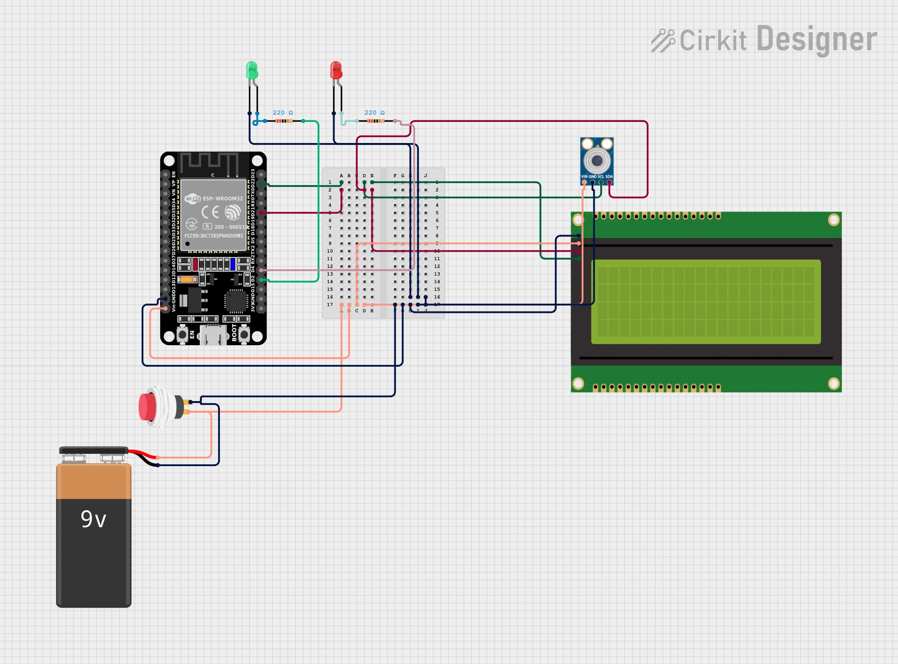
Circuit Documentation
Summary
This circuit is designed to monitor temperature using an MLX90614 infrared temperature sensor and display the readings on a 20x4 I2C LCD panel. The system is powered by a 9V battery and controlled by an ESP32 microcontroller. The circuit also includes two LEDs to indicate system status and temperature anomalies, and a push switch for power control. The ESP32 connects to WiFi and Bluetooth for remote monitoring and control.
Component List
ESP32 (30 pin)
- Description: A powerful microcontroller with WiFi and Bluetooth capabilities.
- Pins: EN, VP, VN, D34, D35, D32, D33, D25, D26, D27, D14, D12, D13, GND, Vin, D23, D22, TX0, RX0, D21, D19, D18, D5, TX2, RX2, D4, D2, D15, 3V3
Resistor (220 Ohms)
- Description: A resistor with a resistance of 220 Ohms.
- Pins: pin1, pin2
LED: Two Pin (red)
- Description: A red LED.
- Pins: cathode, anode
LED: Two Pin (green)
- Description: A green LED.
- Pins: cathode, anode
2Pin Push Switch
- Description: A push switch with two pins.
- Pins: Input +, Output +
20x4 I2C LCD Panel
- Description: An LCD panel with I2C interface.
- Pins: GND, VCC, SDA, SCL
9V Battery
- Description: A 9V battery for powering the circuit.
- Pins: -, +
MLX90614
- Description: An infrared temperature sensor.
- Pins: SDA, SCL, GND, VIN
Wiring Details
ESP32 (30 pin)
- GND: Connected to the cathode of the green LED, cathode of the red LED, GND of the LCD panel, Output + of the push switch, GND of the MLX90614, and - of the 9V battery.
- Vin: Connected to VCC of the LCD panel, Input + of the push switch, VIN of the MLX90614, and + of the 9V battery.
- D22: Connected to SCL of the LCD panel and SCL of the MLX90614.
- D21: Connected to SDA of the LCD panel and SDA of the MLX90614.
- D4: Connected to pin2 of a 220 Ohm resistor.
- D2: Connected to pin2 of another 220 Ohm resistor.
Resistor (220 Ohms)
- pin1: Connected to the anode of the green LED.
- pin2: Connected to D2 of the ESP32.
Resistor (220 Ohms)
- pin1: Connected to the anode of the red LED.
- pin2: Connected to D4 of the ESP32.
LED: Two Pin (red)
- cathode: Connected to GND of the ESP32.
- anode: Connected to pin1 of a 220 Ohm resistor.
LED: Two Pin (green)
- cathode: Connected to GND of the ESP32.
- anode: Connected to pin1 of a 220 Ohm resistor.
2Pin Push Switch
- Input +: Connected to Vin of the ESP32.
- Output +: Connected to GND of the ESP32.
20x4 I2C LCD Panel
- GND: Connected to GND of the ESP32.
- VCC: Connected to Vin of the ESP32.
- SDA: Connected to D21 of the ESP32.
- SCL: Connected to D22 of the ESP32.
9V Battery
- -: Connected to GND of the ESP32.
- +: Connected to Vin of the ESP32.
MLX90614
- SDA: Connected to D21 of the ESP32.
- SCL: Connected to D22 of the ESP32.
- GND: Connected to GND of the ESP32.
- VIN: Connected to Vin of the ESP32.
Code Documentation
#include <Wire.h>
#include <Adafruit_MLX90614.h>
#include <LiquidCrystal_I2C.h>
#include <WiFi.h>
#include <BluetoothSerial.h>

// Define the components
Adafruit_MLX90614 mlx = Adafruit_MLX90614(); // GY-906 DCI sensor
LiquidCrystal_I2C lcd(0x27, 20, 4);          // LCD (20x4)
BluetoothSerial SerialBT;                    // Bluetooth
#define LED1_PIN 2                           // LED 1 for system ON
#define LED2_PIN 4                           // LED 2 for alarm
#define BATTERY_PIN 35                       // Battery monitoring pin

// Variables
float tempThreshold = 140.0; // Default threshold
String material = "FR4 (4.2-4.8)";
float batteryVoltage = 0.0;

// WiFi credentials
const char *ssid = "YOUR_WIFI_SSID";
const char *password = "YOUR_WIFI_PASSWORD";

// Function to initialize WiFi
void setupWiFi() {
  WiFi.begin(ssid, password);
  while (WiFi.status() != WL_CONNECTED) {
    delay(500);
    Serial.println("Connecting to WiFi...");
  }
  Serial.println("Connected to WiFi");
}

// Function to set material properties via Bluetooth or Serial Monitor
void setMaterial(String selectedMaterial) {
  if (selectedMaterial == "FR4 (4.2-4.8)") {
    tempThreshold = 140.0;
  } else if (selectedMaterial == "FR4 (4.5-4.8)") {
    tempThreshold = 170.0;
  } else if (selectedMaterial == "FR4 (3.4-3.8)") {
    tempThreshold = 220.0;
  } else if (selectedMaterial == "PTFE") {
    tempThreshold = 160.0;
  } else if (selectedMaterial == "POLYIMIDE") {
    tempThreshold = 300.0;
  }
  material = selectedMaterial;
}

// Setup function
void setup() {
  Serial.begin(115200);
  SerialBT.begin("TempMonitor"); // Bluetooth device name
  Wire.begin();
  mlx.begin();
  lcd.begin(20, 4); // Initialize the LCD with 20 columns and 4 rows
  lcd.backlight();

  pinMode(LED1_PIN, OUTPUT);
  pinMode(LED2_PIN, OUTPUT);
  pinMode(BATTERY_PIN, INPUT);

  digitalWrite(LED1_PIN, HIGH); // Turn on system status LED
  setupWiFi();                 // Initialize WiFi
  setMaterial("FR4 (4.2-4.8)"); // Default material
}

// Function to read battery voltage
float readBatteryVoltage() {
  int raw = analogRead(BATTERY_PIN);
  return raw * (3.3 / 4095.0) * 2; // Voltage divider factor
}

// Main loop
void loop() {
  float objectTemp = mlx.readObjectTempC();
  batteryVoltage = readBatteryVoltage();

  // Display on LCD
  lcd.setCursor(0, 0);
  lcd.print("Material: ");
  lcd.print(material);
  lcd.setCursor(0, 1);
  lcd.print("Temp: ");
  lcd.print(objectTemp, 1);
  lcd.print(" C");
  lcd.setCursor(0, 2);
  lcd.print("Threshold: ");
  lcd.print(tempThreshold, 1);
  lcd.print(" C");
  lcd.setCursor(0, 3);
  lcd.print("Battery: ");
  lcd.print(batteryVoltage, 2);
  lcd.print(" V");

  // Check for temperature anomaly
  if (objectTemp > tempThreshold) {
    digitalWrite(LED2_PIN, HIGH); // Turn on alarm LED
    SerialBT.println("ALERT: Temperature Anomaly Detected!");
  } else {
    digitalWrite(LED2_PIN, LOW);
  }

  // Check for material selection command via Bluetooth
  if (SerialBT.available()) {
    String command = SerialBT.readString();
    command.trim();
    setMaterial(command);
    SerialBT.println("Material set to: " + material);
  }

  delay(1000); // Delay for stability
}
This code initializes the ESP32, connects to WiFi, and sets up the MLX90614 sensor and LCD display. It continuously reads the temperature and battery voltage, displays the information on the LCD, and checks for temperature anomalies. If an anomaly is detected, it turns on an alarm LED and sends an alert via Bluetooth. The material properties can be set via Bluetooth commands.