
Arduino UNO-Based Sensor Monitoring and GSM Communication System
View and Edit Project In Cirkit Designer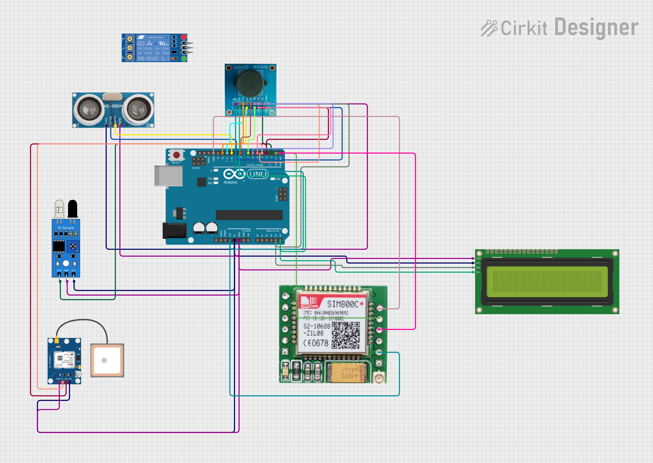
Circuit Documentation
Summary
This document provides a detailed overview of a circuit that includes an Arduino UNO as the central microcontroller, interfaced with various sensors and modules including an Ultrasonic Sensor, an IR Sensor, a GPS NEO 6M module, a 16x2 I2C LCD, a SIM800c GSM Module, and an OV7670 camera module. The circuit is designed to perform multiple functions such as distance measurement, infrared detection, GPS location tracking, GSM communication, and image capture. The Arduino UNO manages these components and facilitates communication between them.
Component List
Arduino UNO
- Microcontroller board based on the ATmega328P
- It has 14 digital input/output pins, 6 analog inputs, a 16 MHz quartz crystal, a USB connection, a power jack, an ICSP header, and a reset button.
KF-301 Relay
- A relay module with a signal input, power, ground, and contact pins (NC, C, NO).
Ultrasonic Sensor
- A sensor that measures distance by emitting ultrasonic waves and measuring the time taken for the echo to return.
IR Sensor
- An infrared sensor capable of detecting infrared signals, often used for proximity or motion detection.
GPS NEO 6M
- A GPS module that provides location data through satellite signals.
16x2 I2C LCD
- A liquid crystal display that can show 16 characters per line and has 2 lines. It uses the I2C communication protocol.
SIM800c GSM Module
- A GSM/GPRS module that allows cellular network connectivity for voice, SMS, and data.
OV7670
- A camera module capable of capturing images and video.
Wiring Details
Arduino UNO
- 5V: Powers the Ultrasonic Sensor, GPS NEO 6M, IR Sensor, and 16x2 I2C LCD.
- D9: Connected to the Trigger pin of the Ultrasonic Sensor.
- D10: Connected to the Echo pin of the Ultrasonic Sensor.
- GND: Common ground for all components.
- 3.3V: Powers the SIM800c GSM Module and OV7670.
- A4 (SDA): I2C data line connected to the OV7670 and 16x2 I2C LCD.
- A5 (SCL): I2C clock line connected to the OV7670 and 16x2 I2C LCD.
- D12: Connected to the HS pin of the OV7670.
- D11: Connected to the VS pin of the OV7670.
- D8: Connected to the D6 pin of the OV7670.
- D7: Connected to the D5 pin of the OV7670.
- D6: Connected to the D4 pin of the OV7670.
- D5: Connected to the D3 pin of the OV7670.
- D4: Connected to the D2 pin of the OV7670 and TX pin of the GPS NEO 6M.
- D3: Connected to the D1 pin of the OV7670 and RX pin of the GPS NEO 6M.
- D2: Connected to the D0 pin of the OV7670 and out pin of the IR Sensor.
- D1 (TX): Connected to the TXD pin of the SIM800c GSM Module.
- D0 (RX): Connected to the RXD pin of the SIM800c GSM Module.
KF-301 Relay
- Signal: (Not connected in the provided net list)
- Power: (Not connected in the provided net list)
- Ground: (Not connected in the provided net list)
- NC: (Not connected in the provided net list)
- C: (Not connected in the provided net list)
- NO: (Not connected in the provided net list)
Ultrasonic Sensor
- +VCC: Powered by the 5V pin of the Arduino UNO.
- Trigger: Connected to the D9 pin of the Arduino UNO.
- Echo: Connected to the D10 pin of the Arduino UNO.
- GND: Common ground with the Arduino UNO.
IR Sensor
- Out: Connected to the D2 pin of the Arduino UNO.
- Gnd: Common ground with the Arduino UNO.
- Vcc: Powered by the 5V pin of the Arduino UNO.
GPS NEO 6M
- VCC: Powered by the 5V pin of the Arduino UNO.
- RX: Connected to the D3 pin of the Arduino UNO.
- TX: Connected to the D4 pin of the Arduino UNO.
- GND: Common ground with the Arduino UNO.
16x2 I2C LCD
- GND: Common ground with the Arduino UNO.
- VCC: Powered by the 5V pin of the Arduino UNO.
- SDA: Connected to the A4 pin of the Arduino UNO.
- SCL: Connected to the A5 pin of the Arduino UNO.
SIM800c GSM Module
- VCC(3.7 - 4.2): Powered by the 3.3V pin of the Arduino UNO.
- GND: Common ground with the Arduino UNO.
- TXD: Connected to the D1 pin of the Arduino UNO.
- RXD: Connected to the D0 pin of the Arduino UNO.
OV7670
- 3.3V: Powered by the 3.3V pin of the Arduino UNO.
- DGND: Common ground with the Arduino UNO.
- D0-D7: Connected to the D2-D9 pins of the Arduino UNO respectively.
- PLK: Connected to the D10 pin of the Arduino UNO.
- XLK: (Not connected in the provided net list)
- VS: Connected to the D11 pin of the Arduino UNO.
- HS: Connected to the D12 pin of the Arduino UNO.
- SCL: Connected to the A5 pin of the Arduino UNO.
- SDA: Connected to the A4 pin of the Arduino UNO.
Documented Code
Arduino UNO Code (sketch.ino)
void setup() {
  // put your setup code here, to run once:

}

void loop() {
  // put your main code here, to run repeatedly:

}
The provided code is a template with empty setup() and loop() functions, which are the entry points for Arduino sketches. The setup() function is called once when the sketch starts and is used for initializing variables, pin modes, starting libraries, etc. The loop() function is called repeatedly and contains the main logic of the sketch.
(Note: The second code entry for the Arduino UNO is empty and thus not included in the documentation.)