Cirkit Designer
Your all-in-one circuit design IDE
Home /
Project Documentation
Arduino UNO Controlled IR Sensor Array with Servo and I2C LCD Display
Circuit Documentation
Summary
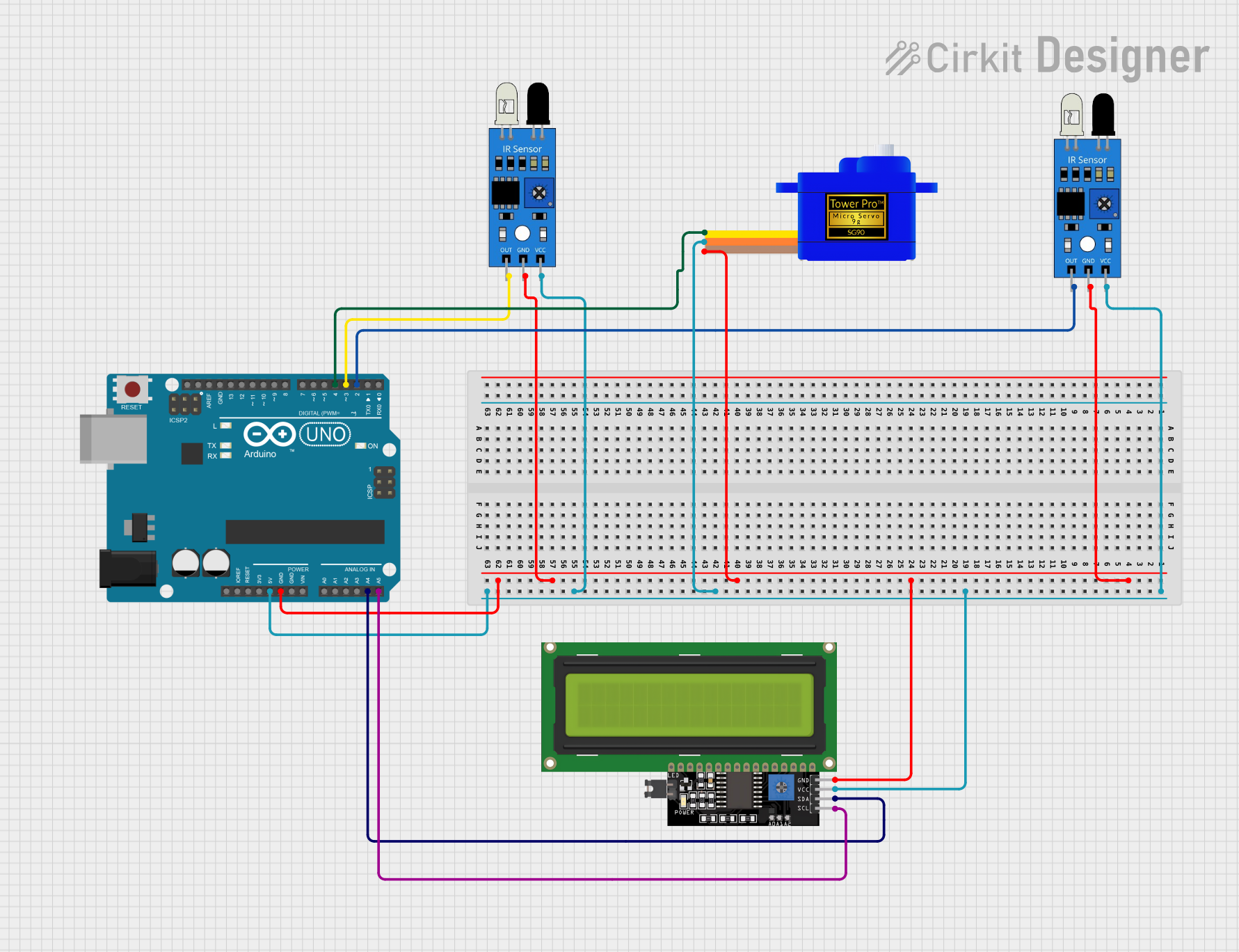
The circuit in question is designed to interface an Arduino UNO microcontroller with a set of peripherals including two IR sensors, a servomotor (SG90), and an LCD Display (16x4 I2C). The IR sensors are used to detect the presence or absence of objects, the servomotor to actuate based on sensor inputs, and the LCD display to provide a user interface or feedback. The Arduino UNO serves as the central processing unit, controlling the sensors, the motor, and the display.
Component List
Arduino UNO
- Description: A microcontroller board based on the ATmega328P.
- Pins: UNUSED, IOREF, Reset, 3.3V, 5V, GND, Vin, A0-A5, SCL, SDA, AREF, D0-D13.
IR Sensor
- Description: An infrared sensor capable of detecting the presence of objects.
- Pins: out, gnd, vcc.
Servomotor SG90
- Description: A small and lightweight servo motor suitable for a broad range of applications.
- Pins: SIG, VCC, GND.
LCD Display 16x4 I2C
- Description: A 16x4 character LCD display with an I2C interface.
- Pins: SCL, SDA, VCC, GND.
Wiring Details
Arduino UNO
- Digital Pin D2: Connected to the 'out' pin of the first IR sensor.
- Digital Pin D3: Connected to the 'out' pin of the second IR sensor.
- Digital Pin D4: Connected to the 'SIG' pin of the Servomotor SG90.
- Analog Pin A4 (SDA): Connected to the 'SDA' pin of the LCD Display.
- Analog Pin A5 (SCL): Connected to the 'SCL' pin of the LCD Display.
- Pin 5V: Connected to the 'vcc' pins of both IR sensors, the 'VCC' pin of the Servomotor SG90, and the 'VCC' pin of the LCD Display.
- Pin GND: Connected to the 'gnd' pins of both IR sensors, the 'GND' pin of the Servomotor SG90, and the 'GND' pin of the LCD Display.
IR Sensor
- out: Connected to the Arduino UNO (Digital Pin D2 for the first sensor, Digital Pin D3 for the second sensor).
- gnd: Connected to the common ground.
- vcc: Connected to the common 5V supply.
Servomotor SG90
- SIG: Connected to the Arduino UNO (Digital Pin D4).
- VCC: Connected to the common 5V supply.
- GND: Connected to the common ground.
LCD Display 16x4 I2C
- SDA: Connected to the Arduino UNO (Analog Pin A4).
- SCL: Connected to the Arduino UNO (Analog Pin A5).
- VCC: Connected to the common 5V supply.
- GND: Connected to the common ground.
Documented Code
Arduino UNO Code (sketch.ino)
void setup() {
  // put your setup code here, to run once:

}

void loop() {
  // put your main code here, to run repeatedly:

}
Additional Notes
- The provided code is a template and does not contain any functional implementation. It needs to be populated with the logic for reading the IR sensors, controlling the servomotor, and updating the LCD display based on the sensor readings and any other required logic.
- The code file named "documentation.txt" is empty and does not contribute to the functionality of the circuit. It may be intended for additional notes or manual documentation by the developer.