
Arduino UNO Controlled RGB LED Strip with Interactive Button
View and Edit Project In Cirkit Designer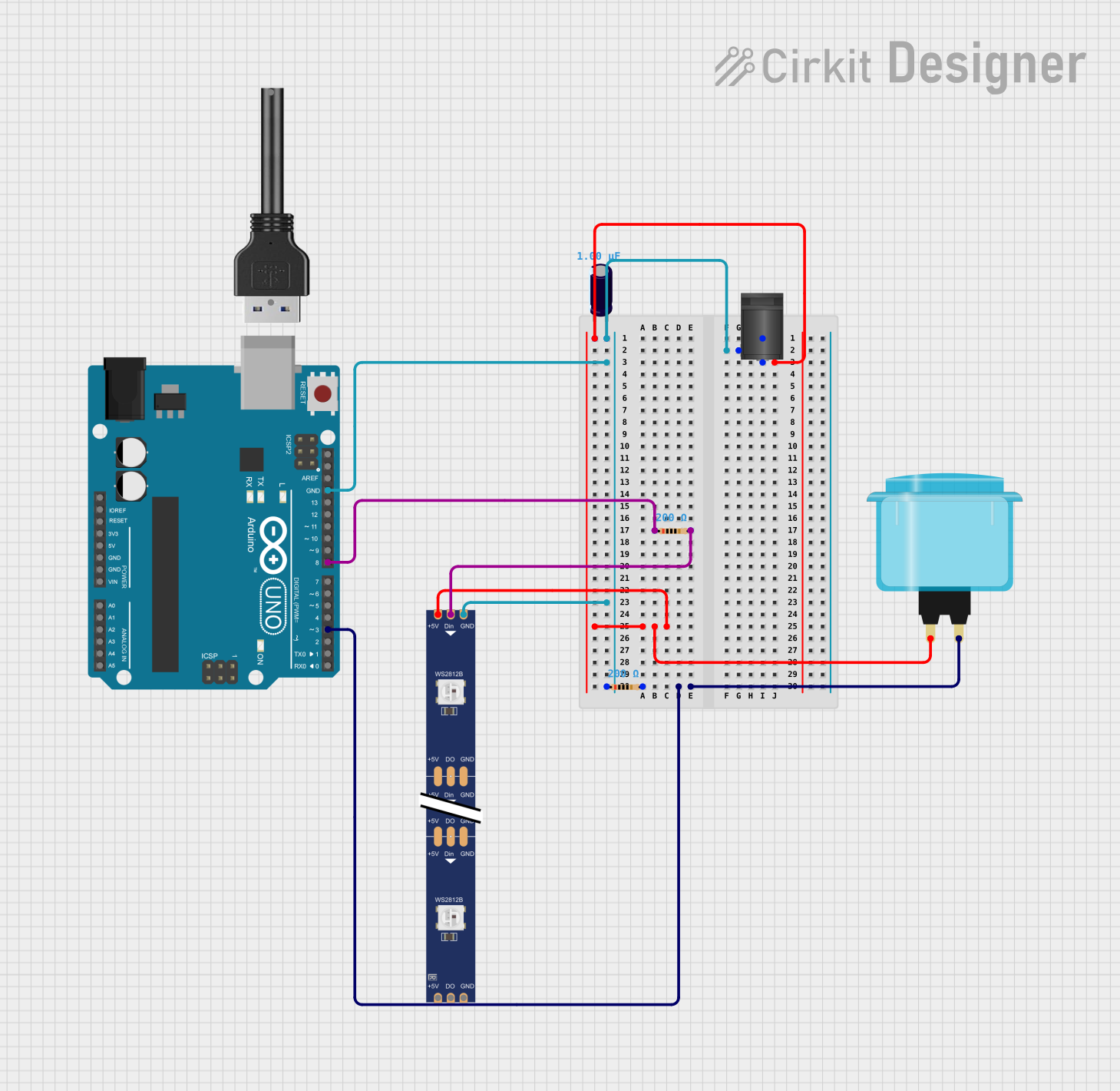
Circuit Documentation
Summary of the Circuit
This circuit is designed around an Arduino UNO microcontroller, which serves as the central processing unit. The circuit includes a 2.1mm DC Barrel Jack for power input, an Electrolytic Capacitor for voltage smoothing, a USB Cable for programming and serial communication, an Arcade Button for user input, and a series of Resistors for current limiting and pull-down purposes. Additionally, a WS2812 RGB LED strip is included for visual output. The circuit is powered by an external power source connected through the DC Barrel Jack, and the Arduino UNO regulates and controls the behavior of the LED strip and reads the state of the Arcade Button.
Component List
Arduino UNO
- Microcontroller board based on the ATmega328P
- It has 14 digital input/output pins, 6 analog inputs, a 16 MHz quartz crystal, a USB connection, a power jack, an ICSP header, and a reset button.
2.1mm DC Barrel Jack
- Power connector for external power supplies
- It has three pins: switch, sleeve, and center.
Electrolytic Capacitor
- Capacitance: 1 µF (microfarads)
- Used for decoupling and noise reduction on the power supply lines.
USB Cable
- Used for programming the Arduino UNO and for serial communication.
Arcade Button (blue)
- A simple push-button switch for user input.
Resistor (200 Ohms)
- Two resistors with a resistance of 200 Ohms each.
- Used for current limiting and pull-down configurations.
WS2812 RGB LED strip
- An addressable LED strip with data in, data out, power, and ground connections.
Wiring Details
Arduino UNO
- GND connected to the sleeve of the DC Barrel Jack, GND of the WS2812 RGB LED strip, and pin1 of a 200 Ohm Resistor.
- D8 connected to the DIN of the WS2812 RGB LED strip through a 200 Ohm Resistor.
- D3 connected to the Arcade Button and pin2 of a 200 Ohm Resistor for pull-down configuration.
2.1mm DC Barrel Jack
- Sleeve connected to the GND of the Arduino UNO, GND of the WS2812 RGB LED strip, and pin1 of a 200 Ohm Resistor.
- Center connected to the positive side of the Electrolytic Capacitor, 5V of the WS2812 RGB LED strip, and the Arcade Button.
Electrolytic Capacitor
- + connected to the sleeve of the DC Barrel Jack.
- - connected to the center of the DC Barrel Jack.
Arcade Button (blue)
- One pin connected to the center of the DC Barrel Jack and D3 of the Arduino UNO through a 200 Ohm Resistor.
Resistor (200 Ohms)
- One resistor with pin1 connected to the GND of the Arduino UNO and pin2 connected to the D3 of the Arduino UNO and the Arcade Button.
- Another resistor with pin1 connected to the D8 of the Arduino UNO and pin2 connected to the DIN of the WS2812 RGB LED strip.
WS2812 RGB LED strip
- DIN connected to D8 of the Arduino UNO through a 200 Ohm Resistor.
- 5V connected to the center of the DC Barrel Jack.
- GND connected to the sleeve of the DC Barrel Jack.
Documented Code
Arduino UNO Code (sketch.ino)
void setup() {
  // put your setup code here, to run once:

}

void loop() {
  // put your main code here, to run repeatedly:

}
Additional Notes (documentation.txt)
No additional code documentation provided.