
Circuit Documentation
Summary of the Circuit
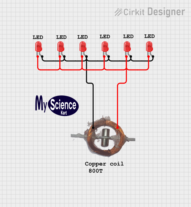
The circuit consists of a series of red two-pin LEDs connected to a copper coil. The LEDs are arranged such that their cathodes are connected to one side of the copper coil, and their anodes are connected to the other side. This configuration suggests that the LEDs are intended to be driven by a current passing through the copper coil, possibly indicating a form of inductive power transfer or a simple series circuit powered by an alternating current source. Since there is no microcontroller code provided, the circuit likely operates purely on the electrical connections without any programmable control logic.
Component List
LEDs: Two Pin (red)
- Description: A standard two-pin light-emitting diode (LED) that emits red light when powered.
- Pins:
cathode: The negative terminal of the LED.anode: The positive terminal of the LED.
- Purpose: To emit light when current flows through the LED from anode to cathode.
Copper Coil
- Description: A coil made of copper wire, which can be used to create a magnetic field when current passes through it or to induce a current when it is placed in a changing magnetic field.
- Pins: Not applicable (no specific pin labels provided).
- Purpose: To serve as an inductive element in the circuit, possibly for transferring power to the LEDs or for creating a magnetic field.
Comments
- Description: Placeholder components that may represent annotations or notes in the circuit design, but do not have a physical presence or electrical function in the circuit.
Logo
- Description: A graphical representation or branding element included in the circuit design for identification or aesthetic purposes.
Wiring Details
LED Wiring
Each LED has two pins, anode and cathode. In this circuit, all the cathodes of the LEDs are connected together, and all the anodes are connected together, forming two separate nets. Each net is then connected to the copper coil, suggesting that the LEDs are wired in parallel with respect to the coil.
LED Connections
- Cathode Net: All LED cathodes are connected to one side of the copper coil.
- Anode Net: All LED anodes are connected to the other side of the copper coil.
Copper Coil Wiring
The copper coil serves as the common connection point for both the anodes and cathodes of the LEDs. It does not have labeled pins, but it is implied that there are two connection points, one for each net.
Documented Code
No code has been provided for any microcontrollers in the circuit. Therefore, there is no programmable control or embedded logic to document. The circuit operates based on the physical wiring and electrical properties of the components.
This documentation provides an overview of the circuit based on the provided information. If there are additional details or specific requirements for the operation of the circuit, further documentation would be necessary to capture those aspects.