
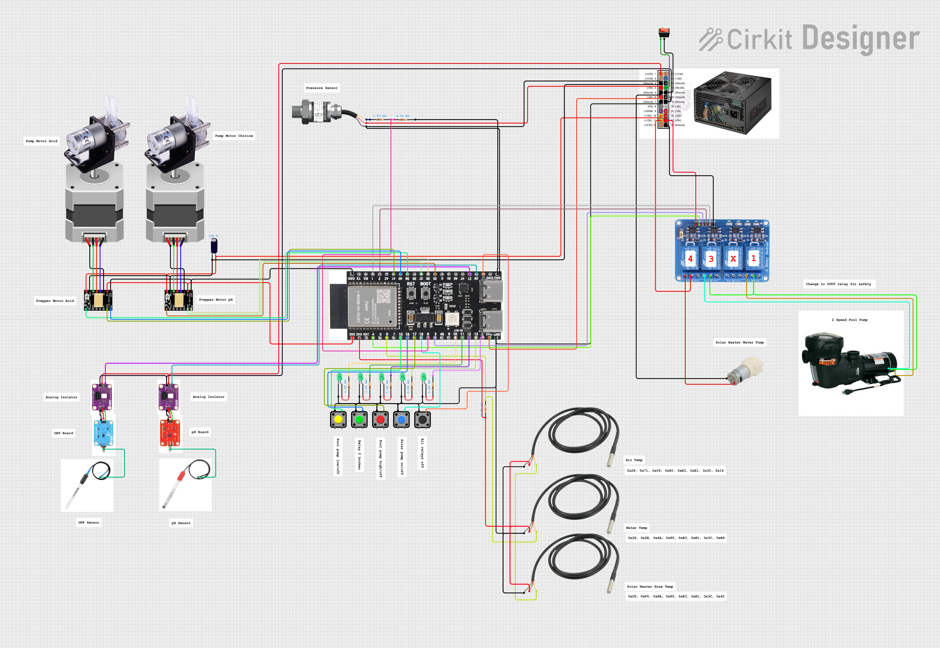
Circuit Documentation
Summary
The circuit in question is designed to monitor and control various aspects of a pool environment. It includes temperature sensors for monitoring water, air, and solar heater temperatures, a water pressure sensor, multiple LEDs for status indication, pushbuttons for manual control, a stepper motor with its driver for mechanical movements, a relay module for controlling high-power devices, and an ESP32-S3 microcontroller for overall control and connectivity.
Component List
Microcontroller
- ESP32-S3-DevKitC-1-N8R2: A development board based on the ESP32-S3 chip, featuring Wi-Fi and Bluetooth capabilities, multiple GPIOs, and support for various communication protocols.
Sensors
- Temperature Sensor: Measures temperature with a digital output that interfaces with the microcontroller.
- Gravity: Analog Water Pressure Sensor: Measures the water pressure and provides an analog output signal.
Actuators
- Stepper Motor (Bipolar): A motor that can be precisely controlled in terms of the steps it takes, typically used for accurate positioning.
- Peristaltic Pump: A type of pump used for moving fluids in a controlled manner.
- 2 Speed Pool Motor: A motor with two-speed settings for pool maintenance.
- Water Pump 12V: A pump for circulating water, operating at 12 volts.
Power Management
- TMC2226 Stepper Driver: A driver module for controlling the stepper motor.
- Relay 4 Channel 5v: A module with four relays to control the on/off state of high-power devices.
- ATX Power Supply: Provides various voltage rails for powering different components of the circuit.
User Interface
- Pushbutton / Red Pushbutton / Tactile Switch Buttons: Manual switches for user input.
- Rocker Switch: A switch to toggle the power state of the circuit.
Indicators
- LED: Two Pin (green): Light-emitting diodes for status indication.
Protection and Stability
- Electrolytic Capacitor: Used for voltage smoothing and filtering.
- Resistor: Used for current limiting and voltage division.
Communication
- Atlas Scientific Analog Isolator: Isolates the analog signal for clean and accurate readings.
- Atlas Scientific ORP Board: Measures oxidation-reduction potential (ORP) for water quality monitoring.
- Atlas Scientific pH Board: Measures the pH level of the water.
Probes
- Atlas Scientific ORP Probe: A probe to measure ORP, typically used in water quality applications.
- Atlas Scientific pH Probe: A probe to measure the pH level of the water.
Wiring Details
Temperature Sensors
- GND: Connected to the ground (GND) of the ESP32-S3 and ATX Power Supply.
- VDD: Connected to the 3.3V output of the ESP32-S3.
- DQ: Connected to GPIO 6 of the ESP32-S3 through a 4.7k Ohm resistor.
Water Pressure Sensor
- Signal: Connected to an analog input of the ESP32-S3.
- VCC: Connected to the 5V output of the ATX Power Supply.
- GND: Connected to the ground (GND) of the ESP32-S3 and ATX Power Supply.
Stepper Motor and Driver
- Motor Coils (A, B, C, D): Connected to the corresponding outputs on the TMC2226 Stepper Driver.
- VMOT: Connected to the +12V output of the ATX Power Supply through an Electrolytic Capacitor.
- GND: Connected to the ground (GND) of the ESP32-S3 and ATX Power Supply.
- VDD: Connected to the 3.3V output of the ESP32-S3.
- STEP, DIR, EN: Connected to GPIOs 37, 36, and 35 of the ESP32-S3, respectively.
Relay Module
- IN1, IN2, IN3, IN4: Connected to GPIOs 1, 2, 3, and 4 of the ESP32-S3.
- VCC: Connected to the 5V output of the ATX Power Supply.
- GND: Connected to the ground (GND) of the ATX Power Supply.
- COM1, COM3: Connected to the common terminal of the 2 Speed Pool Motor.
- NO1, NO3: Connected to the low and high terminals of the 2 Speed Pool Motor.
- NO4: Connected to the + terminal of the 12V Water Pump.
- NC1, NC2, NC3, NC4: Not connected in this circuit.
LEDs
- Anode: Connected to the 3.3V output of the ESP32-S3 through a 1k Ohm resistor.
- Cathode: Connected to the ground (GND) of the ESP32-S3.
Pushbuttons
- Pin 1: Connected to the 3.3V output of the ESP32-S3.
- Pin 4: Connected to GPIOs 15, 16, 17, 18, and 19 of the ESP32-S3.
Rocker Switch
- Input: Connected to the PS-On pin of the ATX Power Supply.
- Output: Connected to the ground (GND) of the ATX Power Supply.
Documented Code
The code provided is for the ESP32-S3 microcontroller and is written in C++ for the Arduino platform. It includes the Blynk IoT platform for remote monitoring and control, OneWire and DallasTemperature libraries for temperature sensing, and WiFi for network connectivity.
The code is structured to perform the following functions:
- Connect to a Wi-Fi network and synchronize time with an NTP server.
- Read temperature data from three temperature sensors and send the readings to the Blynk app.
- Read pressure data from a water pressure sensor and send the readings to the Blynk app.
- Control four relays based on button presses and Blynk app commands.
- Make HTTP GET requests to a weather API and parse the JSON response to obtain and display weather data.
- Implement a scheduler to control the pool pump's operation based on time and temperature conditions.
The code uses GPIOs for interfacing with the buttons, LEDs, relays, and sensors. It also includes error handling for Wi-Fi and HTTP request failures.
Note: The actual code is extensive and includes various functions and routines. For brevity, only the structure and purpose are described here. The full code should be reviewed in the provided file for detailed implementation and comments.