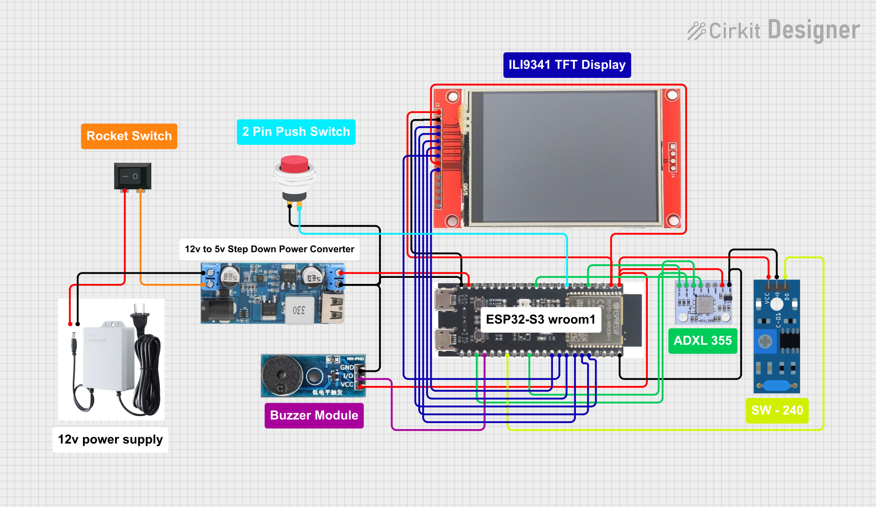
ESP32-S3 Based Vibration Detection System with TFT Display and Power Backup

Circuit Documentation
Summary
This circuit integrates various components to perform a set of functions centered around the ESP32-S3 microcontroller. The circuit includes sensors, a display, power management modules, and user interface elements. The ESP32-S3 serves as the central processing unit, interfacing with an ADXL355 accelerometer, an SW-420 vibration sensor, an ILI9341 TFT display, and a buzzer module. Power is managed through a 12V to 5V step-down converter and a UPS for uninterrupted power supply. User inputs are captured via a push switch and a rocker switch.
Component List
ESP32-S3
- Microcontroller with a variety of GPIO pins for interfacing with sensors, displays, and other peripherals.
- Provides 3.3V and 5V power outputs for other components in the circuit.
SW-420 Vibration Sensor
- Detects vibrations and outputs a digital signal.
Buzzer Module
- Emits an audible alert when triggered by a digital signal.
12V to 5V Step Down Power Converter
- Converts input voltages from 9V-36V down to a stable 5V output.
ADXL355 Accelerometer
- Measures acceleration forces and provides digital outputs for data processing.
ILI9341 TFT Display
- A color display for visual output from the microcontroller.
Rocker Switch (SPST)
- A single-pole single-throw switch used to control power to the circuit.
2Pin Push Switch
- A momentary push switch for user input.
V380 PRO 12V 1.5A Uninterruptible Power Supply Mini UPS
- Provides backup power to ensure the circuit remains operational during power interruptions.
Wiring Details
ESP32-S3
3v3pin provides power to the ADXL355, SW-420 Vibration Sensor, and ILI9341 TFT Display.5Vpin is connected to the 5V output from the step-down converter.GNDpin is a common ground for the step-down converter, push switch, ILI9341 TFT display, buzzer module, ADXL355, and SW-420 Vibration Sensor.- GPIO pins are used for data communication with the ADXL355, ILI9341 TFT display, SW-420 Vibration Sensor, and buzzer module.
SW-420 Vibration Sensor
vccpin connected to the 3.3V output from the ESP32-S3.Groundpin connected to the common ground.Digital outputconnected to the GPIO48 of the ESP32-S3.
Buzzer Module
Vccpin connected to the 3.3V output from the ESP32-S3.GNDpin connected to the common ground.I/Opin connected to the GPIO20 of the ESP32-S3.
12V to 5V Step Down Power Converter
5v OUTPUTconnected to the 5V input of the ESP32-S3.GNDconnected to the common ground.VIN+connected to the Rocker Switch (SPST).VIN-connected to the Positive pin of the UPS.
ADXL355 Accelerometer
VCCpin connected to the 3.3V output from the ESP32-S3.GNDpin connected to the common ground.CS/SCL,SCK,MO/SDA,MI/ASpins connected to corresponding GPIO pins on the ESP32-S3 for SPI communication.
ILI9341 TFT Display
VCCandLEDpins connected to the 3.3V output from the ESP32-S3.GNDpin connected to the common ground.CS,RESET,DC/RS,SDI,SCK,SDOpins connected to corresponding GPIO pins on the ESP32-S3 for SPI communication and control.
Rocker Switch (SPST)
1pin connected to theVIN+of the step-down converter.2pin connected to the Negative pin of the UPS.
2Pin Push Switch
Input +pin connected to theGNDof the step-down converter.Output +pin connected to the GPIO15 of the ESP32-S3.
V380 PRO 12V 1.5A Uninterruptible Power Supply Mini UPS
Positivepin connected to theVIN-of the step-down converter.Negativepin connected to the2pin of the Rocker Switch (SPST).
Documented Code
No code has been provided for the microcontroller. The documentation of the code would typically include a description of the functionality implemented, setup and loop functions for an Arduino-based microcontroller, or initialization and main execution loop for other microcontrollers, along with comments explaining the purpose of each section of the code.