
WiFi-Controlled Basket-Carrying Robot with GPS and GSM Notification
View and Edit Project In Cirkit Designer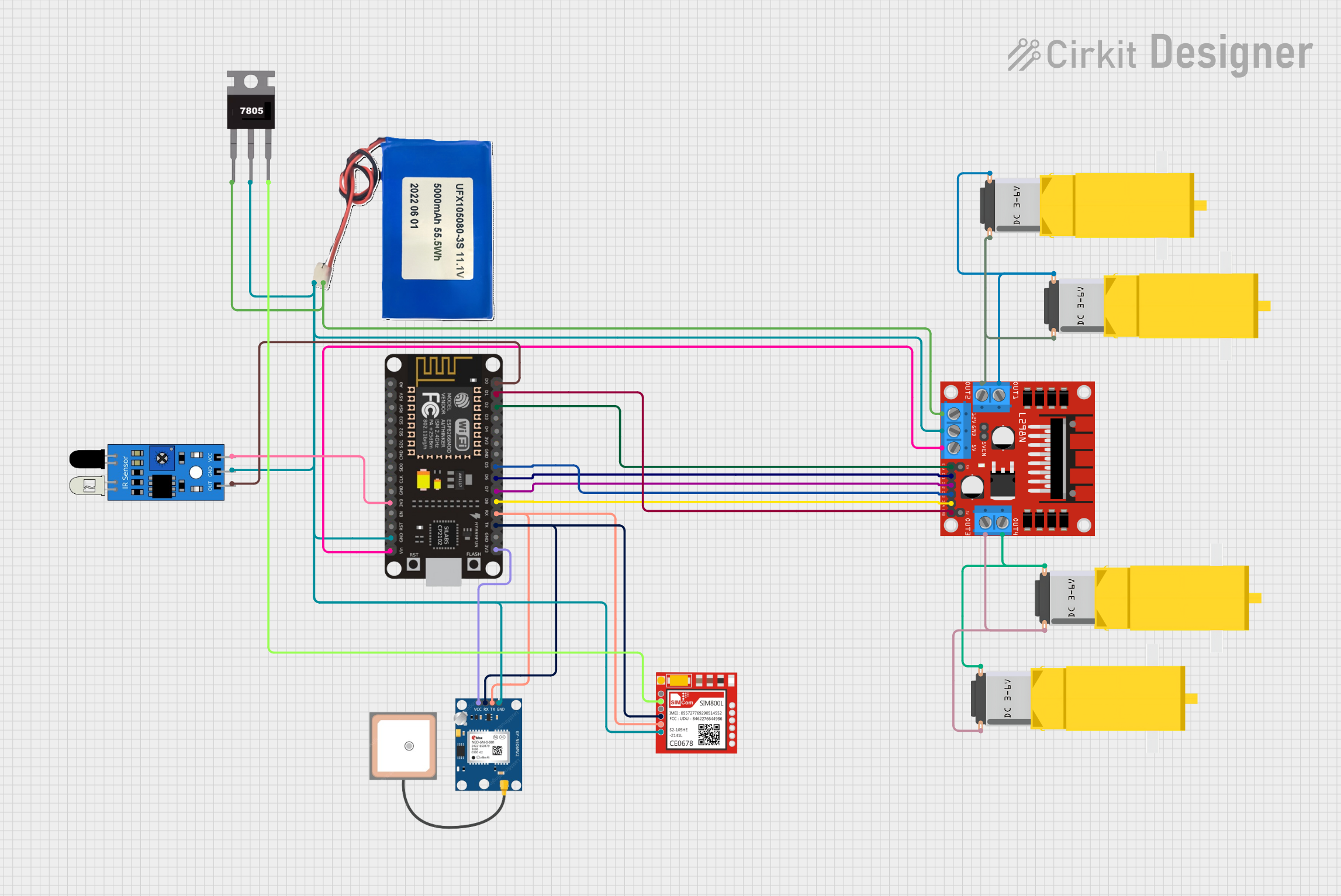
Circuit Documentation
Summary
This circuit is designed to control a 4-wheeled WiFi car with a basket. It features an IR sensor for detecting when the basket is full, which then triggers the system to send the car's location and a message to the user via GPS and GSM modules. The core of the control system is an ESP8266 NodeMCU microcontroller, which interfaces with a GPS module (NEO 6M), a GSM module (Sim800l), and an L298N DC motor driver to control the gearmotors attached to the wheels.
Component List
Gearmotor DC / Motorreductor
- Description: DC gearmotors used for driving the wheels of the car.
- Pins: Pin1, Pin2
Sim800l
- Description: GSM module for sending SMS messages.
- Pins: NET, RST, VCC, RXD, TXD, GND
GPS NEO 6M
- Description: GPS module for obtaining the car's location.
- Pins: VCC, RX, TX, GND
IR Sensor
- Description: Infrared sensor for detecting when the basket is full.
- Pins: Out, Gnd, Vcc
Li-ion 5000mAh Battery
- Description: Power source for the circuit.
- Pins: 11.1V, GND
ESP8266 NodeMCU
- Description: Microcontroller used for controlling the car's functions.
- Pins: D0, D1, D2, D3, D4, 3V3, GND, D5, D6, D7, D8, RX, TX, A0, RSV, SD3, SD2, SD1, CMD, SD0, CLK, EN, RST, VIN
L298N DC Motor Driver
- Description: Motor driver for controlling the speed and direction of the gearmotors.
- Pins: OUT1, OUT2, 12V, GND, 5V, OUT3, OUT4, 5V-ENA-JMP-I, 5V-ENA-JMP-O, +5V-J1, +5V-J2, ENA, IN1, IN2, IN3, IN4, ENB
7805 Voltage Regulator
- Description: Regulates voltage to 5V for the GSM module.
- Pins: Vin, Gnd, Vout
Wiring Details
Gearmotor DC / Motorreductor
- Pin1: Connected to L298N DC motor driver OUT1 or OUT4.
- Pin2: Connected to L298N DC motor driver OUT2 or OUT3.
Sim800l
- NET: Not connected in the provided net list.
- RST: Not connected in the provided net list.
- VCC: Connected to 7805 Voltage Regulator Vout.
- RXD: Connected to GPS NEO 6M TX and ESP8266 NodeMCU RX.
- TXD: Connected to GPS NEO 6M RX and ESP8266 NodeMCU TX.
- GND: Common ground with other components.
GPS NEO 6M
- VCC: Connected to ESP8266 NodeMCU 3V3.
- RX: Connected to Sim800l TXD and ESP8266 NodeMCU TX.
- TX: Connected to Sim800l RXD and ESP8266 NodeMCU RX.
- GND: Common ground with other components.
IR Sensor
- Out: Connected to ESP8266 NodeMCU D0.
- Gnd: Common ground with other components.
- Vcc: Connected to ESP8266 NodeMCU 3V3.
Li-ion 5000mAh Battery
- 11.1V: Connected to 7805 Voltage Regulator Vin and L298N DC motor driver 12V.
- GND: Common ground with other components.
ESP8266 NodeMCU
- D0: Connected to IR Sensor Out.
- D1: Connected to L298N DC motor driver ENB.
- D2: Connected to L298N DC motor driver ENA.
- D3, D4: Used for GSM module communication.
- D5: Connected to L298N DC motor driver IN3.
- D6: Connected to L298N DC motor driver IN1.
- D7: Connected to L298N DC motor driver IN2.
- D8: Connected to L298N DC motor driver IN4.
- 3V3: Powers GPS NEO 6M and IR Sensor.
- GND: Common ground with other components.
- RX: Connected to GPS NEO 6M TX and Sim800l RXD.
- TX: Connected to GPS NEO 6M RX and Sim800l TXD.
- VIN: Connected to L298N DC motor driver 5V.
L298N DC Motor Driver
- OUT1, OUT2, OUT3, OUT4: Connected to Gearmotor DC / Motorreductor Pin1 and Pin2.
- 12V: Powered by Li-ion 5000mAh Battery 11.1V.
- GND: Common ground with other components.
- 5V: Powers ESP8266 NodeMCU VIN.
- ENA, ENB: Controlled by ESP8266 NodeMCU D2 and D1.
- IN1, IN2, IN3, IN4: Controlled by ESP8266 NodeMCU D6, D7, D5, D8.
7805 Voltage Regulator
- Vin: Powered by Li-ion 5000mAh Battery 11.1V.
- Gnd: Common ground with other components.
- Vout: Powers Sim800l VCC.
Documented Code
/*
 * This Arduino Sketch controls a 4-wheeled WiFi car with a basket. An IR sensor
 * detects when the basket is full, triggering the system to send the car's
 * location and a message to the user via GPS and GSM modules.
 */

#include <SoftwareSerial.h>

// Pin definitions
#define IN1 D6
#define IN2 D7
#define IN3 D5
#define IN4 D8
#define ENA D2
#define ENB D1
#define IR_SENSOR D0

// GPS and GSM serial connections
SoftwareSerial gpsSerial(RX, TX); // GPS NEO 6M
SoftwareSerial gsmSerial(D3, D4); // Sim800l

void setup() {
  // Initialize serial communications
  Serial.begin(115200);
  gpsSerial.begin(9600);
  gsmSerial.begin(9600);

  // Initialize motor control pins
  pinMode(IN1, OUTPUT);
  pinMode(IN2, OUTPUT);
  pinMode(IN3, OUTPUT);
  pinMode(IN4, OUTPUT);
  pinMode(ENA, OUTPUT);
  pinMode(ENB, OUTPUT);

  // Initialize IR sensor pin
  pinMode(IR_SENSOR, INPUT);

  // Initialize motors to off
  digitalWrite(ENA, LOW);
  digitalWrite(ENB, LOW);
}

void loop() {
  // Check IR sensor
  if (digitalRead(IR_SENSOR) == HIGH) {
    // Basket is full, send location and message
    sendLocationAndMessage();
  }

  // Add motor control logic here
}

void sendLocationAndMessage() {
  // Get GPS location
  String location = getGPSLocation();

  // Send message via GSM
  gsmSerial.println("AT+CMGF=1"); // Set SMS mode to text
  delay(1000);
  gsmSerial.println("AT+CMGS=\"+1234567890\""); // Replace with user number
  delay(1000);
  gsmSerial.print("Basket is full. Location: ");
  gsmSerial.print(location);
  delay(1000);
  gsmSerial.write(26); // ASCII code for Ctrl+Z to send SMS
  delay(1000);
}

String getGPSLocation() {
  String location = "";
  while (gpsSerial.available()) {
    char c = gpsSerial.read();
    location += c;
  }
  return location;
}
This code is responsible for the operation of the WiFi car. It initializes the serial communication with the GPS and GSM modules, sets up the motor control pins, and reads the IR sensor to detect when the basket is full. Upon detection, it retrieves the GPS location and sends an SMS message with the location to a predefined user number.